Chair covers developed around the frame and its access points.
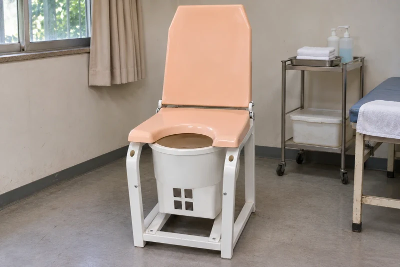
Fiberglass seat, back and lower covers developed around your chair frame, with sample fitting, prepared openings and coordinated exterior finishes.
Upper and lower panels share a coordinated exterior while retaining the openings and removal paths the equipment needs.
- We make
- Seat, back and base covers
- We coordinate
- Frame and movement review
- You receive
- Samples and production sets
Bring the visible covers and underlying frame together.
A treatment chair combines visible upper covers with a lower body around the frame and mechanisms. The cover set needs a consistent appearance while leaving the openings and removal access required by the equipment design.
Upper and lower covers around one frame
Separate visible sections need to follow the equipment geometry and each other.
Openings meeting the underlying structure
Cutouts and fastener access have to clear the frame members and specified fittings.
Panels removed in a defined sequence
Cover joints must leave a practical assembly and service-removal route.
How we customize the parts.
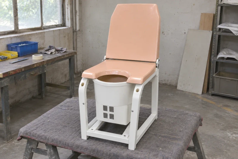
Upper and lower body shapes
Seat, back and lower sections follow the exterior design and the underlying frame. Separate colors can be specified for the upper surfaces and base covers.
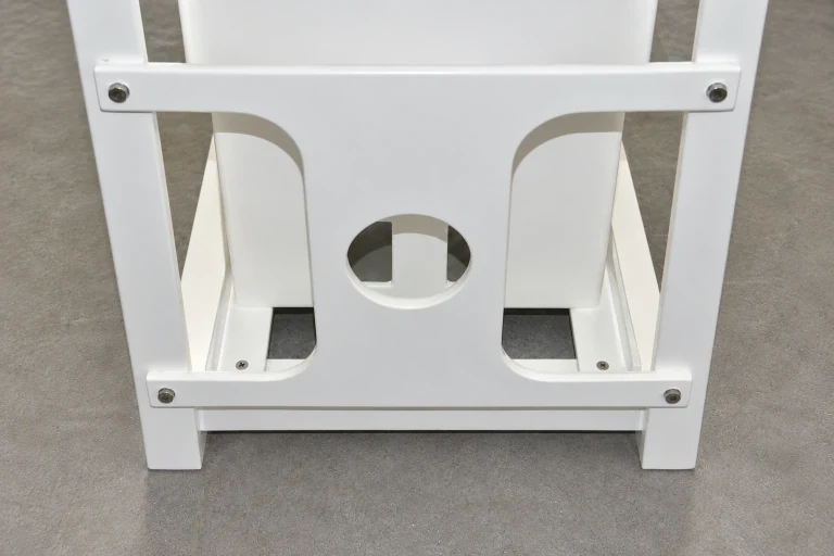
Openings and fastener access
Circular openings, side cutouts and mounting preparations follow your equipment drawings. Their positions account for the frame members and fasteners that the covers must fit around.
Panel joints and removal
Cover divisions and edge shapes follow the assembly and service sequence. Your equipment team can review how each sample part fits and comes off the frame.
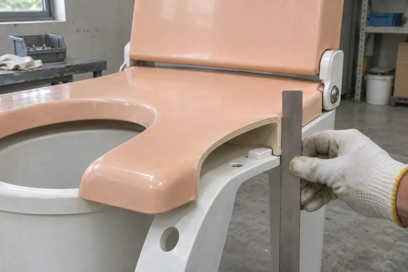
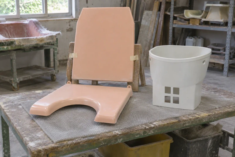
Make parts for fitting
We mold and trim the sample covers, preparing the specified openings and attachment areas. Your team checks the set on the equipment and returns any requested cover changes. After the cover design is accepted, we produce the required sets. Visible surfaces, cutouts and edges are checked and protected for delivery.
A matched set that can be reviewed on the frame.
The first cover set gives the equipment team a shared reference for panel fit, openings and removal access. Upper and lower surfaces follow the agreed appearance while their interfaces are reviewed against the same frame.
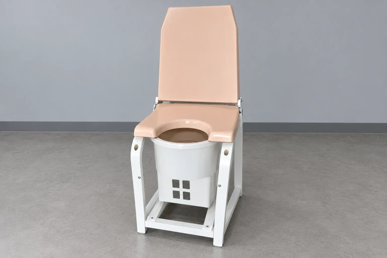
Covers reviewed as one set
Upper and lower panels follow the same equipment frame.
Removal access considered early
Joints and fastener areas follow the service sequence.
A coordinated visible surface appearance
The selected upper and lower colors guide the supplied cover set.
Dimensions and design options
- Material
- Molded FRP covers
- Application
- Treatment chair and examination bed exteriors
- Interfaces
- Clearances, fixings and cutouts from your drawings
- Supply scope
- Covers only; mechanism and device approvals by others
Chair and bed-cover components
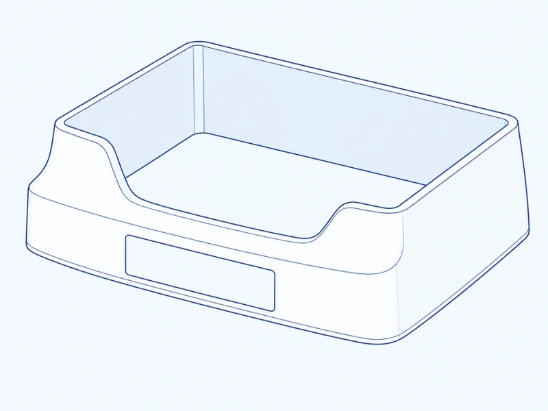
Lower base skirt
An open-top skirt fits around the lower frame and provides the specified foot-control openings.

Telescoping lift shroud
Overlapping sections cover the lift column throughout the travel range specified for the equipment.
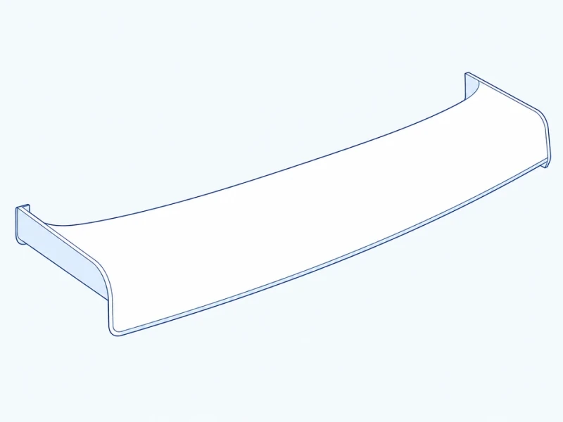
Underside bed cover
A shaped underside cover provides the actuator and cable cutouts shown in your drawing.
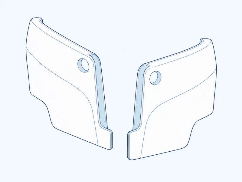
Split side panels
Separate left and right panels fit around the selected hinge or lift layout.
Chair and bed cover references
Stationary skirt and moving frame
The side view measures the stationary skirt’s overall length and its height at the left end. The marked gap lies between the skirt and the moving frame at the illustrated position; the complete movement envelope determines the required clearance.
Open-top skirt and service cutouts
The open-top skirt is shaped to the underside of your chair or bed, with frame fixing areas and foot-control openings placed around the actuator layout.