Expert FRP Manufacturer

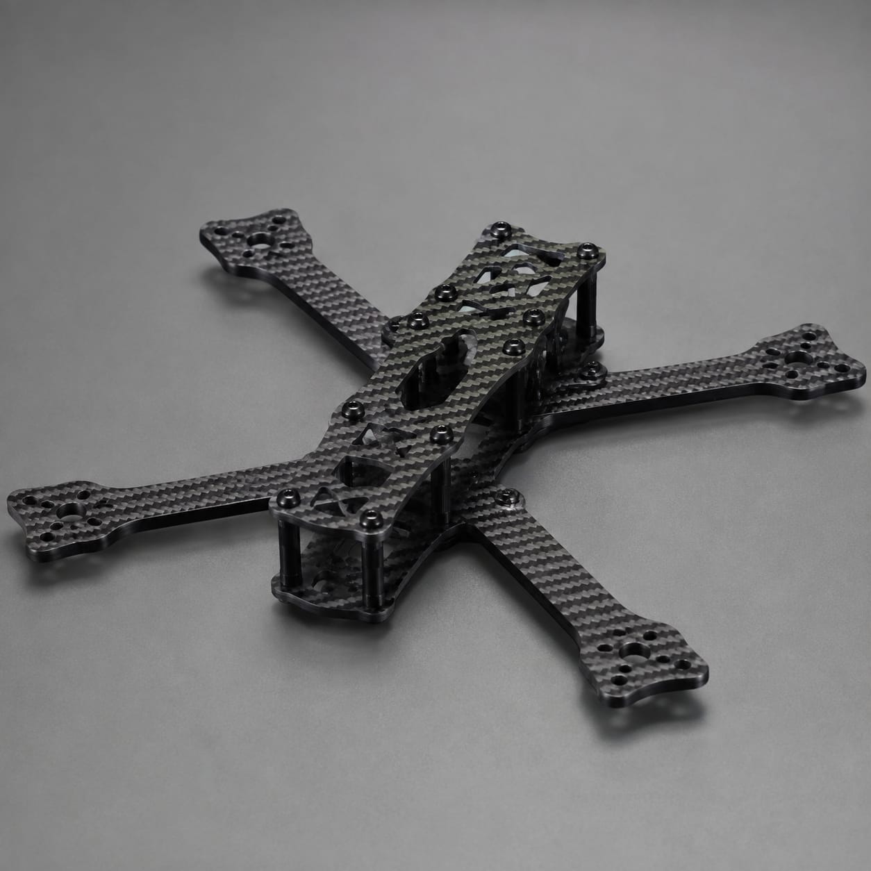
Carbon Fiber Drone Frame

Developed for multirotor UAVs and aerial inspection platforms, this drone frame combines project-specific composite construction with arm layout, motor spacing, center-plate stack, and payload position. Attachment and service details are resolved against the buyer's equipment before manufacturing begins.

Carbon Fiber Drone Frame

Production Scope

Custom Manufacturing

Material

Carbon Fiber Composite

Finish

Custom Surface System

Order Type

Prototype or Batch

How we make it

Propulsion and Payload Layout Review to Motor Pattern and Stack Alignment Check

The route is built around the actual assembly: define arm layout, motor spacing, center-plate stack, and payload position, manufacture using directional laminates with reinforced arm roots, motor pads, stack mounts, and landing attachments, and record arm geometry, motor-hole pattern, stack alignment, payload datum, and trimmed edges before packing.

01

Propulsion and Payload Layout Review

We review arm layout, motor spacing, center-plate stack, and payload position in the context of multirotor UAVs and aerial inspection platforms. The same review records the declared thrust arrangement, vibration sources, landing conditions, and operating environment and any customer-controlled acceptance criteria.

  • Define arm layout, motor spacing, center-plate stack, and payload position
  • Record the declared thrust arrangement, vibration sources, landing conditions, and operating environment
02

Frame Layup and Arm-Root Build

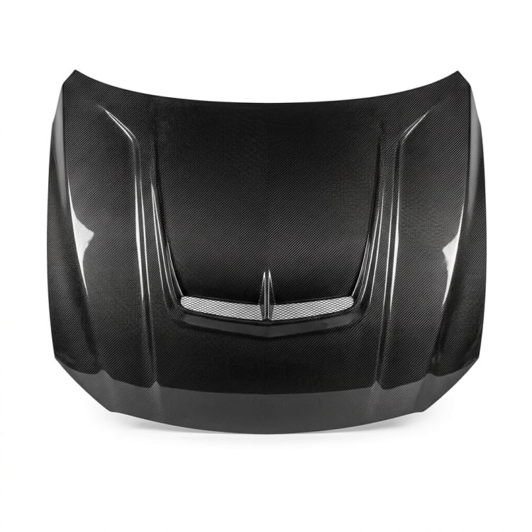
The part is produced using directional laminates with reinforced arm roots, motor pads, stack mounts, and landing attachments. Particular care is given to battery retention, landing gear, controller mounts, cable paths, and service openings so later drilling, assembly, and service remain practical.

  • Apply directional laminates with reinforced arm roots, motor pads, stack mounts, and landing attachments
  • Build for battery retention, landing gear, controller mounts, cable paths, and service openings
03

Motor Pattern and Stack Alignment Check

Before packing, the agreed inspection covers arm geometry, motor-hole pattern, stack alignment, payload datum, and trimmed edges. Results are recorded to the level specified in the purchase package, without implying system certification.

  • Check arm geometry, motor-hole pattern, stack alignment, payload datum, and trimmed edges
  • Protect the finished drone frame for shipment

Scope at a glance

Applications + Custom Options

Applications

Where this drone frame adds value

This drone frame provides a lightweight chassis sized for the customer's propulsion, payload, and control stack. It is most relevant when arm layout, motor spacing, center-plate stack, and payload position must work with battery retention, landing gear, controller mounts, cable paths, and service openings under the declared thrust arrangement, vibration sources, landing conditions, and operating environment.

  • Built for multirotor UAVs and aerial inspection platforms
  • Provides a lightweight chassis sized for the customer's propulsion, payload, and control stack
  • Defined by arm layout, motor spacing, center-plate stack, and payload position
  • Evaluated against the declared thrust arrangement, vibration sources, landing conditions, and operating environment

Custom options

Options for the drone frame

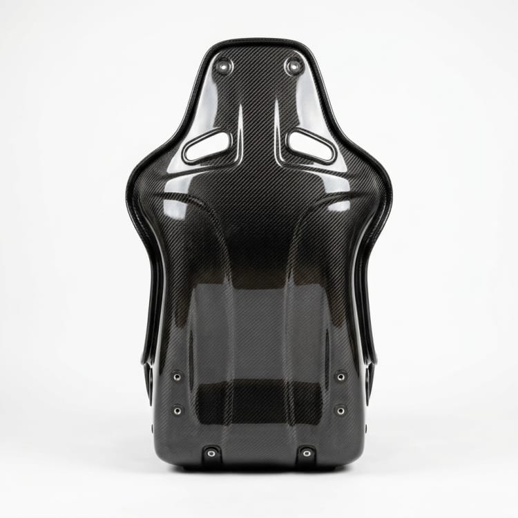
Buyers can define arm layout, motor spacing, center-plate stack, and payload position. The quotation can also include battery retention, landing gear, controller mounts, cable paths, and service openings, plus surface, inspection, quantity, and packing requirements appropriate to the program.

  • Shape and envelope: arm layout, motor spacing, center-plate stack, and payload position
  • Assembly details: battery retention, landing gear, controller mounts, cable paths, and service openings
  • Service conditions: the declared thrust arrangement, vibration sources, landing conditions, and operating environment
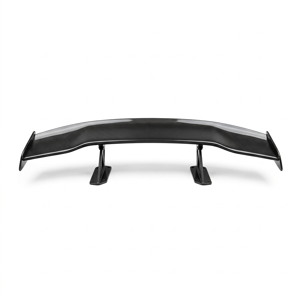
  • Visible finish, color or weave intent, inspection records, packing, and order quantity

Browse nearby applications using the same category and manufacturing approach.

Need to know

Common buyer questions

Which UAV layout files should we provide?

Provide the current CAD model or drawing plus the mating assembly. We use those records to establish arm layout, motor spacing, center-plate stack, and payload position and flag any missing datum or clearance before manufacture.

Can the frame retain our motor and controller mounting patterns?

Yes, where the supplied assembly data supports it. We review battery retention, landing gear, controller mounts, cable paths, and service openings and return any unresolved fit or access question before the build is released.

How are vibration-sensitive payloads considered?

The buyer should define vibration sources and spectra, payload mounts, the isolation strategy, allowable deflection, and flight and landing loads. We can coordinate mounting zones, local laminate provisions, and clearances with the released design, while final flight and payload-performance validation remains the buyer's responsibility.