Expert FRP Manufacturer

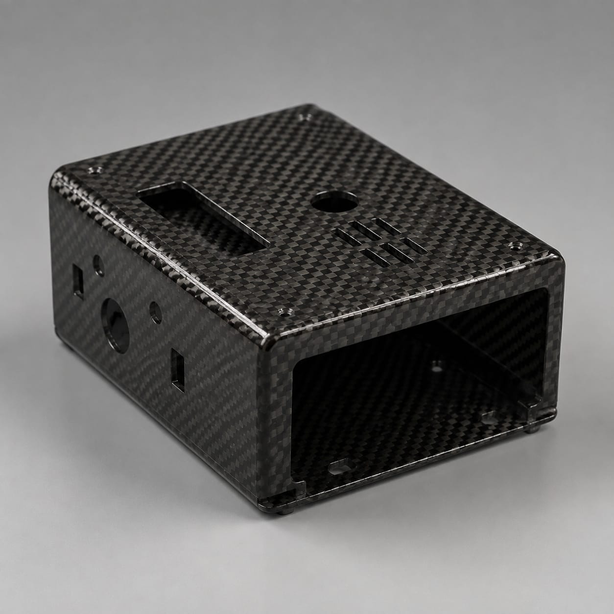
Carbon Fiber Electronics Shell

Built for portable instruments, sensing equipment, robotics, and premium electronics, this custom electronics shell follows shell split line, outer form, connector apertures, and internal clearance. Its composite build also accounts for the mating equipment and service details instead of using a generic catalog envelope.

Carbon Fiber Electronics Shell

Production Scope

Custom Manufacturing

Material

Carbon Fiber Composite

Finish

Custom Surface System

Order Type

Prototype or Batch

How we make it

Electronics Package and Split-Line Review to Closure and Connector Aperture Check

The work moves from the customer's package and heat release, radio-frequency needs, impact risk, service frequency, and the installation environment through molded shells with local reinforcement at inserts, apertures, hinges, and fastening points, followed by checks of mating edges, connector cutouts, internal mounting points, closure fit, and visible surfaces.

01

Electronics Package and Split-Line Review

We review shell split line, outer form, connector apertures, and internal clearance in the context of portable instruments, sensing equipment, robotics, and premium electronics. The same review records heat release, radio-frequency needs, impact risk, service frequency, and the installation environment and any customer-controlled acceptance criteria.

  • Define shell split line, outer form, connector apertures, and internal clearance
  • Record heat release, radio-frequency needs, impact risk, service frequency, and the installation environment
02

Shell Molding and Insert Preparation

The part is produced using molded shells with local reinforcement at inserts, apertures, hinges, and fastening points. Particular care is given to PCB bosses, inserts, control openings, vents, seals, and assembly sequence so later drilling, assembly, and service remain practical.

  • Apply molded shells with local reinforcement at inserts, apertures, hinges, and fastening points
  • Build for PCB bosses, inserts, control openings, vents, seals, and assembly sequence
03

Closure and Connector Aperture Check

Before packing, the agreed inspection covers mating edges, connector cutouts, internal mounting points, closure fit, and visible surfaces. Results are recorded to the level specified in the purchase package, without implying system certification.

  • Check mating edges, connector cutouts, internal mounting points, closure fit, and visible surfaces
  • Protect the finished electronics shell for shipment

Scope at a glance

Applications + Custom Options

Applications

Where this electronics shell adds value

This electronics shell provides a lightweight outer housing for a defined electronics package. It is most relevant when shell split line, outer form, connector apertures, and internal clearance must work with PCB bosses, inserts, control openings, vents, seals, and assembly sequence under heat release, radio-frequency needs, impact risk, service frequency, and the installation environment.

  • Built for portable instruments, sensing equipment, robotics, and premium electronics
  • Provides a lightweight outer housing for a defined electronics package
  • Defined by shell split line, outer form, connector apertures, and internal clearance
  • Evaluated against heat release, radio-frequency needs, impact risk, service frequency, and the installation environment

Custom options

Options for the electronics shell

Buyers can define shell split line, outer form, connector apertures, and internal clearance. The quotation can also include PCB bosses, inserts, control openings, vents, seals, and assembly sequence, plus surface, inspection, quantity, and packing requirements appropriate to the program.

  • Shape and envelope: shell split line, outer form, connector apertures, and internal clearance
  • Assembly details: PCB bosses, inserts, control openings, vents, seals, and assembly sequence
  • Service conditions: heat release, radio-frequency needs, impact risk, service frequency, and the installation environment
  • Visible finish, color or weave intent, inspection records, packing, and order quantity

Browse nearby applications using the same category and manufacturing approach.

Need to know

Common buyer questions

Can carbon fiber be used around antennas and wireless modules?

Yes, but conductive carbon fiber can shield or attenuate radio-frequency signals. The buyer should define antenna locations, frequency bands, clearance zones, and the validation method so the released design can incorporate nonconductive RF windows, external antenna zones, or other specified provisions. Final wireless-performance testing remains the buyer's responsibility.

How are PCB mounts and connector openings incorporated?

Those details can be included in the manufacturing brief. The review covers PCB bosses, inserts, control openings, vents, seals, and assembly sequence, with dimensions and hardware supplied or confirmed by the buyer.

Can the housing be opened for routine service?

Yes. Buyer-controlled drawings can define removable covers, fastener locations, connector access, cable clearances, and the required service-removal path. The completed electronics assembly and service procedure must be verified by the buyer.