Expert FRP Manufacturer

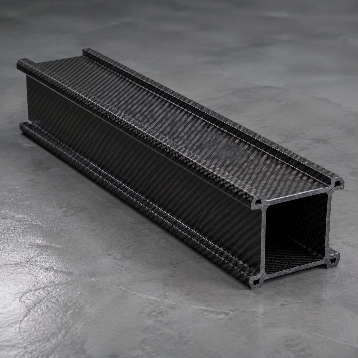
Carbon Fiber Machine Beam

For precision automation, moving gantries, metrology, printing, and pick-and-place equipment, the machine beam is made to the customer's package rather than a stock size. The brief covers beam section, span, rail datum, end geometry, and allowable equipment envelope, assembly details, and the relevant service environment.

Carbon Fiber Machine Beam

Production Scope

Custom Manufacturing

Material

Carbon Fiber Composite

Finish

Custom Surface System

Order Type

Prototype or Batch

How we make it

Axis Duty and Rail Datum Review to Reference Face and End-Plate Check

Drawings and use conditions set the build basis. Manufacturing then uses directional laminate construction with local reinforcement beneath rails, inserts, and end connections, with the completed part reviewed for rail datum, insert locations, end-face relationship, straightness references, and finish.

01

Axis Duty and Rail Datum Review

We review beam section, span, rail datum, end geometry, and allowable equipment envelope in the context of precision automation, moving gantries, metrology, printing, and pick-and-place equipment. The same review records the stated motion profile, supported mass, thermal environment, stiffness targets, and machine duty and any customer-controlled acceptance criteria.

  • Define beam section, span, rail datum, end geometry, and allowable equipment envelope
  • Record the stated motion profile, supported mass, thermal environment, stiffness targets, and machine duty
02

Beam Layup and Insert Integration

The part is produced using directional laminate construction with local reinforcement beneath rails, inserts, and end connections. Particular care is given to linear-rail pattern, end plates, inserts, cable route, hard stops, and carriage clearance so later drilling, assembly, and service remain practical.

  • Apply directional laminate construction with local reinforcement beneath rails, inserts, and end connections
  • Build for linear-rail pattern, end plates, inserts, cable route, hard stops, and carriage clearance
03

Reference Face and End-Plate Check

Before packing, the agreed inspection covers rail datum, insert locations, end-face relationship, straightness references, and finish. Results are recorded to the level specified in the purchase package, without implying system certification.

  • Check rail datum, insert locations, end-face relationship, straightness references, and finish
  • Protect the finished machine beam for shipment

Scope at a glance

Applications + Custom Options

Applications

Where this machine beam adds value

This machine beam provides a low-mass structural member for a machine axis or measurement assembly. It is most relevant when beam section, span, rail datum, end geometry, and allowable equipment envelope must work with linear-rail pattern, end plates, inserts, cable route, hard stops, and carriage clearance under the stated motion profile, supported mass, thermal environment, stiffness targets, and machine duty.

  • Built for precision automation, moving gantries, metrology, printing, and pick-and-place equipment
  • Provides a low-mass structural member for a machine axis or measurement assembly
  • Defined by beam section, span, rail datum, end geometry, and allowable equipment envelope
  • Evaluated against the stated motion profile, supported mass, thermal environment, stiffness targets, and machine duty

Custom options

Options for the machine beam

Buyers can define beam section, span, rail datum, end geometry, and allowable equipment envelope. The quotation can also include linear-rail pattern, end plates, inserts, cable route, hard stops, and carriage clearance, plus surface, inspection, quantity, and packing requirements appropriate to the program.

  • Shape and envelope: beam section, span, rail datum, end geometry, and allowable equipment envelope
  • Assembly details: linear-rail pattern, end plates, inserts, cable route, hard stops, and carriage clearance
  • Service conditions: the stated motion profile, supported mass, thermal environment, stiffness targets, and machine duty
  • Visible finish, color or weave intent, inspection records, packing, and order quantity

Browse nearby applications using the same category and manufacturing approach.

Need to know

Common buyer questions

What machine-axis data should accompany the CAD model?

Provide the current CAD model or drawing plus the mating assembly. We use those records to establish beam section, span, rail datum, end geometry, and allowable equipment envelope and flag any missing datum or clearance before manufacture.

Can inserts follow our linear-rail and carriage pattern?

Yes, where the supplied assembly data supports it. We review linear-rail pattern, end plates, inserts, cable route, hard stops, and carriage clearance and return any unresolved fit or access question before the build is released.

How are thermal and stiffness requirements handled?

The buyer's motion profile, supported mass, temperature range and gradients, stiffness and deflection targets, rail datums, and duty cycle guide the released laminate, section, insert, and interface details. Final thermal-error analysis and machine-level stiffness validation remain the buyer's responsibility.