Expert FRP Manufacturer

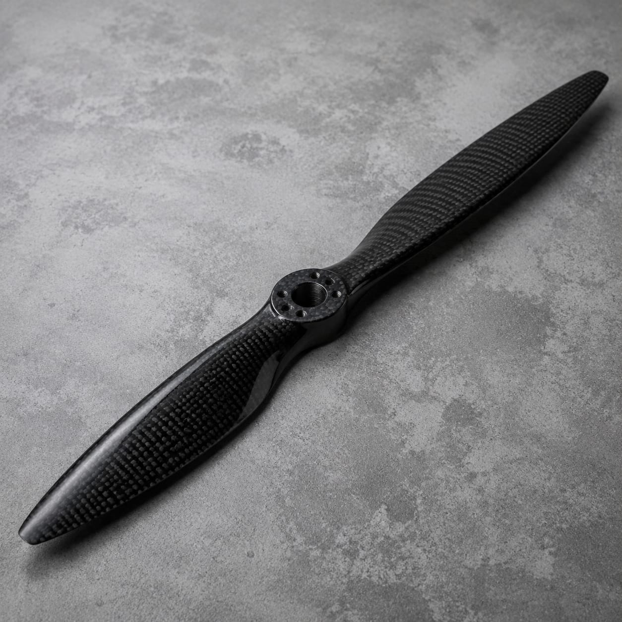
Carbon Fiber Propeller Blade

Developed for prototype propulsion systems and instrumented air or marine test rigs, this propeller blade combines project-specific composite construction with airfoil sections, pitch distribution, sweep, blade length, and leading-edge form. Attachment and service details are resolved against the buyer's equipment before manufacturing begins.

Carbon Fiber Propeller Blade

Production Scope

Custom Manufacturing

Material

Carbon Fiber Composite

Finish

Custom Surface System

Order Type

Prototype or Batch

How we make it

Aerodynamic Definition and Root Review to Profile, Pitch, and Hub-Fit Check

The route is built around the actual assembly: define airfoil sections, pitch distribution, sweep, blade length, and leading-edge form, manufacture using directional composite layup with concentrated reinforcement through the root and customer-defined edge protection, and record section profiles, pitch references, root fit, mass records if requested, surface condition, and traceable inspection data before packing.

01

Aerodynamic Definition and Root Review

We review airfoil sections, pitch distribution, sweep, blade length, and leading-edge form in the context of prototype propulsion systems and instrumented air or marine test rigs. The same review records the buyer's rotational speed, medium, fatigue case, erosion risk, and test program and any customer-controlled acceptance criteria.
  • Define airfoil sections, pitch distribution, sweep, blade length, and leading-edge form
  • Record the buyer's rotational speed, medium, fatigue case, erosion risk, and test program
02

Blade Layup and Root Consolidation

The part is produced using directional composite layup with concentrated reinforcement through the root and customer-defined edge protection. Particular care is given to root geometry, hub attachment, pitch datum, rotation direction, and assembly clearance so later drilling, assembly, and service remain practical.

  • Apply directional composite layup with concentrated reinforcement through the root and customer-defined edge protection
  • Build for root geometry, hub attachment, pitch datum, rotation direction, and assembly clearance
03

Profile, Pitch, and Hub-Fit Check

Before packing, the agreed inspection covers section profiles, pitch references, root fit, mass records if requested, surface condition, and traceable inspection data. Results are recorded to the level specified in the purchase package, without implying system certification.

  • Check section profiles, pitch references, root fit, mass records if requested, surface condition, and traceable inspection data
  • Protect the finished propeller blade for shipment

Scope at a glance

Applications + Custom Options

Applications

Where this propeller blade adds value

This propeller blade follows a customer-engineered design with controlled geometry and a defined root attachment. It is most relevant when airfoil sections, pitch distribution, sweep, blade length, and leading-edge form must work with root geometry, hub attachment, pitch datum, rotation direction, and assembly clearance under the buyer's rotational speed, medium, fatigue case, erosion risk, and test program.

  • Built for prototype propulsion systems and instrumented air or marine test rigs
  • Follows a customer-engineered design with controlled geometry and a defined root attachment
  • Defined by airfoil sections, pitch distribution, sweep, blade length, and leading-edge form
  • Evaluated against the buyer's rotational speed, medium, fatigue case, erosion risk, and test program
Custom options

Options for the propeller blade

Buyers can define airfoil sections, pitch distribution, sweep, blade length, and leading-edge form. The quotation can also include root geometry, hub attachment, pitch datum, rotation direction, and assembly clearance, plus surface, inspection, quantity, and packing requirements appropriate to the program.

  • Shape and envelope: airfoil sections, pitch distribution, sweep, blade length, and leading-edge form
  • Assembly details: root geometry, hub attachment, pitch datum, rotation direction, and assembly clearance
  • Service conditions: the buyer's rotational speed, medium, fatigue case, erosion risk, and test program
  • Visible finish, color or weave intent, inspection records, packing, and order quantity

Browse nearby applications using the same category and manufacturing approach.

Need to know

Common buyer questions

Which blade definition and operating data are required?

We can work from CAD, drawings, a controlled scan, or a reference part as appropriate. The source needs to capture airfoil sections, pitch distribution, sweep, blade length, and leading-edge form and the key assembly references.

Can the root be made for our existing hub?

The part can be adapted to the customer's installation. We check root geometry, hub attachment, pitch datum, rotation direction, and assembly clearance against the mating equipment, maintenance route, and available clearances.

Who is responsible for propulsion-system validation?

The buyer and its designated design or certification authority are responsible. Our scope follows released manufacturing and inspection data; aerodynamic and structural substantiation, fatigue and overspeed testing, hub integration, balancing criteria, and propulsion-system approval remain with the buyer.