Expert FRP Manufacturer

FRP Dental Imaging System Housing

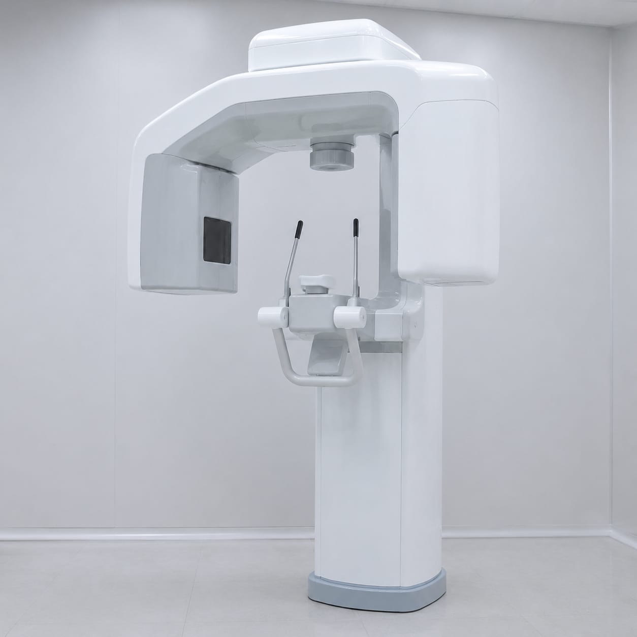
Developed for panoramic or cone-beam dental imaging systems that move around the patient, this housing organizes rotating-head covers and column shrouds around the OEM equipment package. We mold and trim the FRP sections to preserve the rotation envelope and sensor openings, service access, and specified cosmetic surfaces for device assembly.

FRP Dental Imaging System Housing

Production Scope

Custom FRP Dental Imaging System Housing

Material

FRP Composite Shell

Finish

Project-Specified Painted or Coated Surface

Order Type

Prototype to Repeat Batch

How we make it

Dental Imaging System Housing Enclosure Development and Production

Production begins with the OEM equipment envelope and the rotation envelope. The housing assembly is divided into moldable sections, formed, trimmed, fitted with specified hardware provisions, inspected to buyer references, and packed for device assembly.

01

Dental Imaging System Housing Package and Service Review

Review the device envelope, rotating-head covers, column shrouds, a control bezel, base panels, and positioning surrounds, and the requirements for the rotation envelope, sensor openings, chin-rest connection, cables, frame mounts, handles, and service access. The OEM data must also identify cosmetic zones, panel splits, trim references, mounting features, ventilation, cables, and service-removal paths.

  • Review rotating-head covers and column shrouds against the equipment package
  • Mark access, ventilation, cable, and mounting features
02

Dental Imaging System Housing Molding and Feature Preparation

Prepare molds for the released shell divisions, form the composite sections, and add the specified reinforcement, inserts, openings, joints, and trim features around the rotation envelope and sensor openings.

  • Form the rotating-head covers and adjoining covers
  • Reinforce attachment and service areas
03

Dental Imaging System Housing Inspection and OEM Handoff

Check the housing against buyer references for dimensions, panel fit, the rotation envelope, edge quality, and cosmetic finish. Protect each section for transport and the OEM's downstream assembly and device-level validation.

  • Check shell dimensions and access-panel fit
  • Inspect the rotation envelope and visible surfaces

Scope at a glance

Applications + Custom Options

Applications

Dental Imaging System Housing Application and OEM Scope

This enclosure is intended for panoramic or cone-beam dental imaging systems that move around the patient. It provides shaped external covers and specified assembly features while leaving device architecture, performance, cleaning strategy, safety, and regulatory decisions with the medical equipment OEM.

  • Designed around panoramic or cone-beam dental imaging systems that move around the patient.
  • Visible and removable sections may include rotating-head covers, column shrouds, a control bezel, base panels, and positioning surrounds.
  • Shell divisions must preserve the rotation envelope, sensor openings, chin-rest connection, cables, frame mounts, handles, and service access.
  • Dental Imaging System Housing programs may progress from appearance and fit-review shells to pilot units and repeat orders after rotating-head covers and column shrouds and the related inspection data are controlled by the OEM.

Custom options

Dental Imaging System Housing Shell and Access Options

OEM CAD, packaging data, drawings, or a reference shell can define the Dental Imaging System Housing outer form. Panel boundaries and removable areas are then developed around rotating-head covers and column shrouds, with clearances and service paths governed by the rotation envelope and sensor openings.

  • Define rotating-head covers, column shrouds, a control bezel, base panels, and positioning surrounds.
  • Lay out removable panels and openings around the rotation envelope, sensor openings, chin-rest connection, cables, frame mounts, handles, and service access.
  • Specify bosses, bonded or installed inserts, brackets, fastener positions, edge radii, panel joints, and trim references around rotating-head covers and the rotation envelope.
  • Set the buyer's color, gloss, texture, marking areas, coating system, and cosmetic acceptance references for the Dental Imaging System Housing.

Browse nearby applications using the same category and manufacturing approach.

Need to know

Common buyer questions

Can the Dental Imaging System Housing be made from our CAD or equipment package?

Yes. OEM CAD, packaging data, drawings, scan data, or a reference shell can define rotating-head covers and column shrouds. We review mold release, part divisions, trim access, and laminate access before confirming the manufacturing approach.

How are access, ventilation, and mounting features handled on the Dental Imaging System Housing?

The OEM must define locations and clearances for the rotation envelope, sensor openings, chin-rest connection, cables, frame mounts, handles, and service access. We can mold or trim the specified openings, prepare removable covers, and add agreed inserts or brackets to the released drawings; the OEM verifies those features in the assembled device.

Does GFIND validate the completed medical device fitted with the Dental Imaging System Housing?

No. We manufacture and inspect the Dental Imaging System Housing to buyer specifications, including the released features for the rotation envelope and sensor openings. Device risk management, cleaning and disinfection validation, electrical and mechanical safety, regulatory compliance, and completed-device verification remain with the medical equipment OEM.