Expert FRP Manufacturer

FRP Water Slide Splash Trough

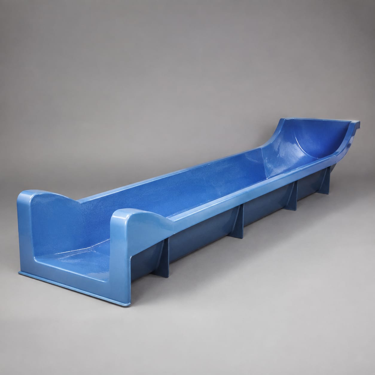
Designed for slide exits that use a guided runout instead of a large landing basin, this water slide splash trough is shaped around trough width and floor fall. We manufacture the FRP parts from project drawings, paying close attention to upstream slide alignment and supports, clean section joints, and a durable visual finish.

FRP Water Slide Splash Trough

Production Scope

Custom FRP Water Slide Splash Trough

Material

FRP Composite

Finish

Project-Specified Gel Coat or Paint

Order Type

New Build or Replacement Program

How we make it

Water Slide Splash Trough Engineering-to-Production Workflow

For this water slide splash trough, production follows the released trough width and upstream slide alignment requirements. Molds, laminate details, section joints, finish checks, and transport supports are developed around that geometry.

01

Water Slide Splash Trough Route and Site Review

Review the intended use, rider path or basin function, trough width, floor fall, sidewalls, entry transition, drain points, and end geometry, and the site requirements for upstream slide alignment, supports, section joints, water return, and rider-exit area. Unresolved structural, hydraulic, or installation inputs are identified for the project team.

  • Confirm trough width and floor fall
  • Record upstream slide alignment and supports
02

Water Slide Splash Trough Molds and FRP Lamination

Produce molds that hold the released trough width and related transitions, then laminate the sections with the specified reinforcement, flanges, openings, and embedded details. Joint preparation reflects the needs of upstream slide alignment.

  • Establish mold splits around trough width
  • Form reinforcement and molded connection details
03

Water Slide Splash Trough Fit Checks and Dispatch

Verify the finished water slide splash trough against the inspection references for trough width and floor fall, joint faces, edges, finish, and upstream slide alignment and supports. Supports and wrapping are arranged around the agreed lift and transport method.

  • Check section geometry and connection features
  • Inspect the water-facing and public-facing finish

Scope at a glance

Applications + Custom Options

Applications

Where the Water Slide Splash Trough Fits

This solution is intended for slide exits that use a guided runout instead of a large landing basin. It is most useful when the attraction footprint, rider path, water system, supports, and installation access are defined early enough to shape manufacturable sections.

  • Application: slide exits that use a guided runout instead of a large landing basin.
  • Functional form: trough width, floor fall, sidewalls, entry transition, drain points, and end geometry.
  • Project connections to resolve: upstream slide alignment, supports, section joints, water return, and rider-exit area.
  • The water slide splash trough can form part of a new attraction or replace selected FRP sections when upstream alignment, supports, and adjoining geometry are documented.

Custom options

Water Slide Splash Trough Geometry and Finish Options

The water slide splash trough can be derived from a route model, basin layout, site survey, or verified replacement section. Design review concentrates on trough width and floor fall and how the FRP parts meet upstream slide alignment and supports.

  • Set the trough width, floor fall, sidewalls, entry transition, drain points, and end geometry.
  • Define how the product meets upstream slide alignment, supports, section joints, water return, and rider-exit area.
  • Apply the project palette to the water slide splash trough through selected gel-coat or paint colors, gloss, texture, edge treatment, and deliberate color breaks.
  • Place mold and shipment splits where they preserve trough width, provide workable flanges, and remain compatible with site lifting access.

Browse nearby applications using the same category and manufacturing approach.

Need to know

Common buyer questions

Can the Water Slide Splash Trough be adapted to our site layout?

Yes. We can develop manufacturable FRP sections around the supplied footprint and requirements for trough width, floor fall, sidewalls, entry transition, drain points, and end geometry. A reliable quotation needs drawings or a model that also shows upstream slide alignment, supports, section joints, water return, and rider-exit area.

What information is needed before the Water Slide Splash Trough enters production?

Please provide the released route or basin geometry, including trough width and floor fall, together with support locations, joints, upstream slide alignment and supports, water and drainage information, finish requirements, and site access. Replacement projects should also include verified survey data or a reference section.

Who confirms the structure, hydraulics, and rider safety for the Water Slide Splash Trough?

For the Water Slide Splash Trough, the buyer and its qualified project engineers must confirm final structural adequacy, hydraulic performance, rider safety, installation engineering, and all applicable regulations and site requirements. GFIND fabricates the composite parts to released manufacturing documents covering trough width, floor fall, sidewalls, entry transition, drain points, and end geometry, including the specified provisions for upstream slide alignment, supports, section joints, water return, and rider-exit area; no project certification is implied.