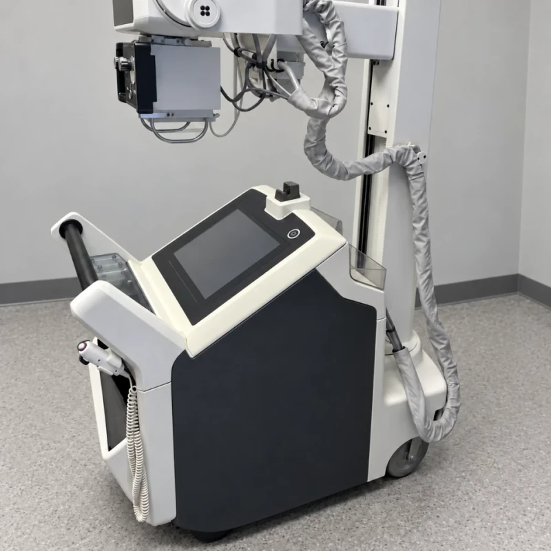
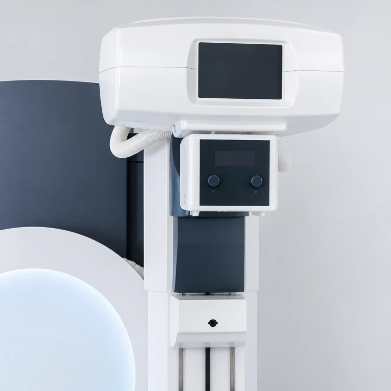
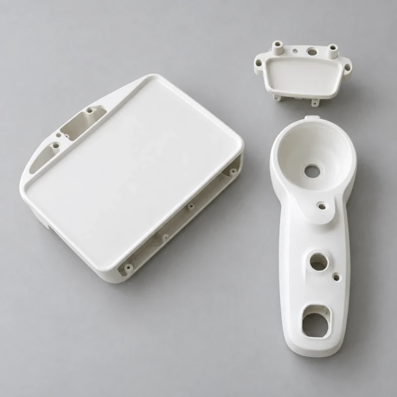
Custom FRP Dental Imaging System Housings
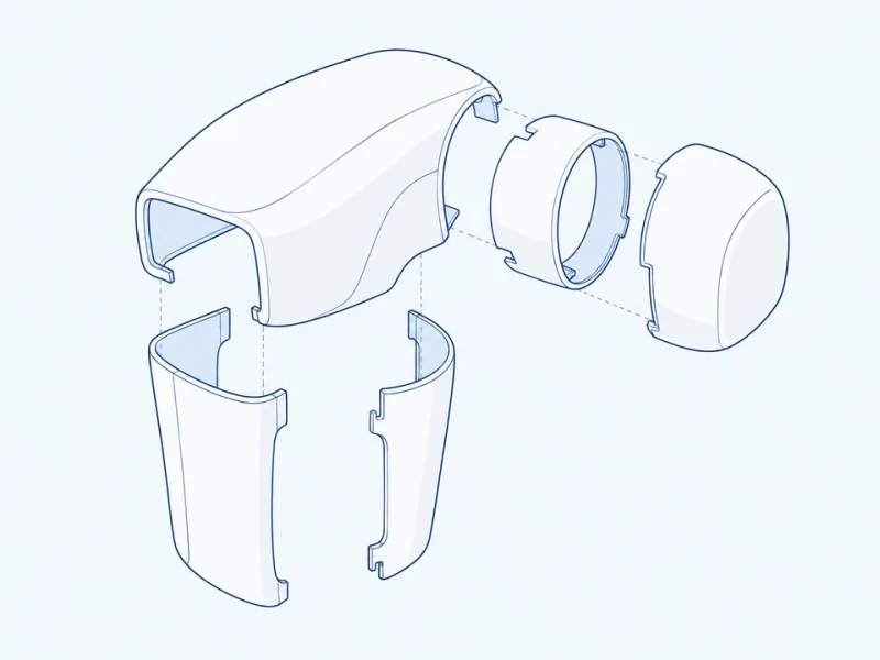
Fiberglass head shells and arm fairings form the exterior of a dental imaging unit. A curved main shell meets a removable rear cap, while collars and split covers surround the positioning joints and links. The cover shapes can follow the equipment's movement and conceal their mounting tabs.
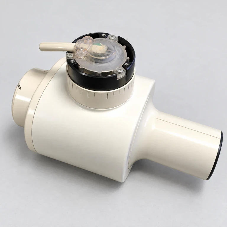
Opened imaging-head assembly reference showing the curved cover and rotary-joint interface. The shell and rear cap follow your head model; the joint mechanism and imaging hardware are separate.
Image credit: ·
Dental imaging cover parts
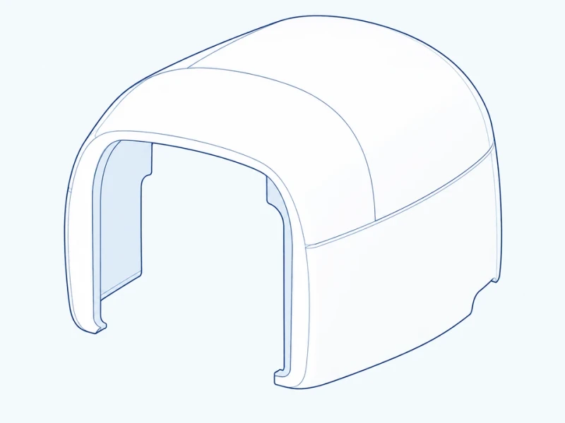
Rounded main cover
A rounded head shell has the specified forward opening and a rear edge for the separate cap.
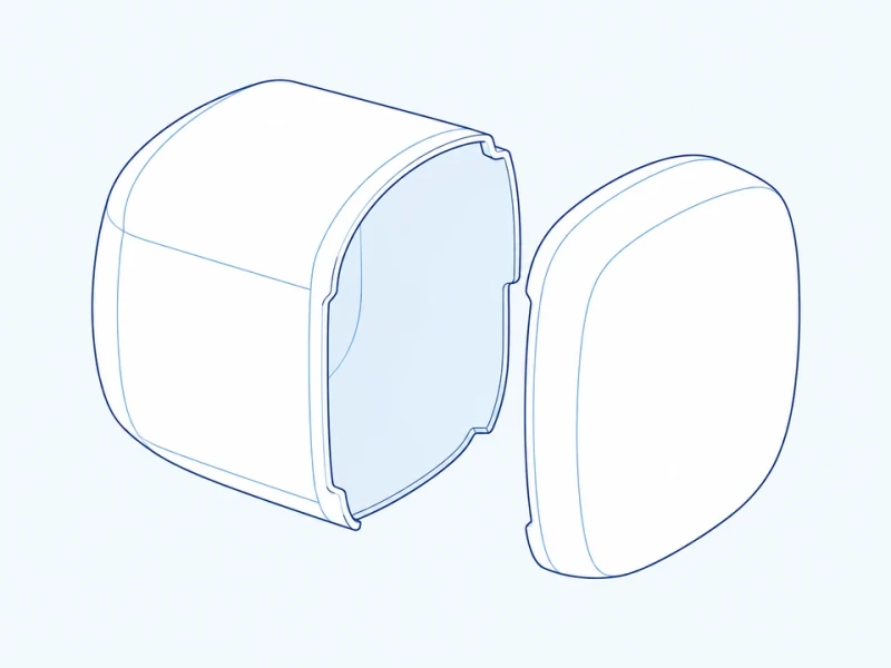
Separate rear cap
A removable curved rear cap closes the main body with a matching return depth.
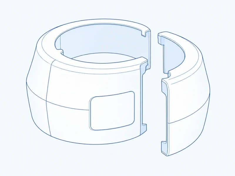
Rotary-joint surround
An exterior collar surrounds the pivot opening with separate sections for access to the joint.
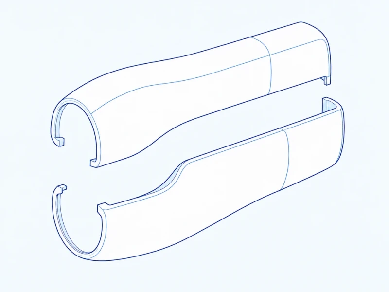
Split positioning-arm fairing
Two fairing pieces enclose the positioning link, with end shapes following the pivot movement.
Customize the dental imaging covers
Curved shell molds
The head-body contour, rear-cap depth and arm profiles follow your exterior CAD model.
Pivot and mounting details
Openings surround the pivot assemblies, while concealed mounting areas and joining tabs attach the covers without exposed fixings on the main faces.
Matched curved surfaces
Opening edges, color and gloss are finished to match across the head, cap and arm fairings.
Dental imaging cover details
Head body and rotary opening
Cover length spans the head shell and its forward extension. Body height runs from the curved main-body crown to its lower edge, excluding the upper pivot collar. Pivot-opening width sets the space around the separate rotary-joint assembly.
Head, collar and split fairings
The head shell meets its removable rear cap at a returned edge. Split fairings close around the arm links and meet the separate pivot collars.