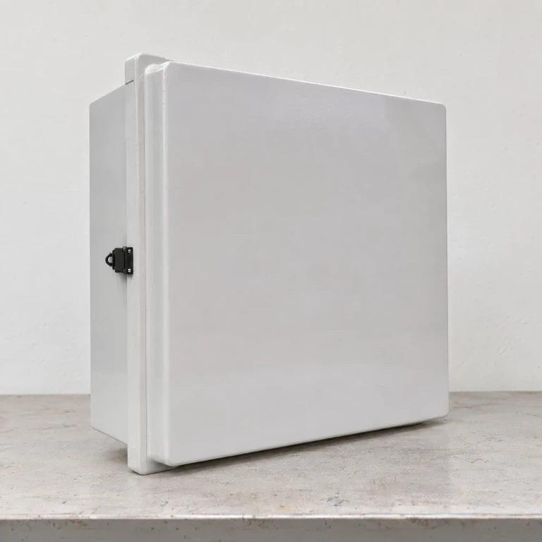
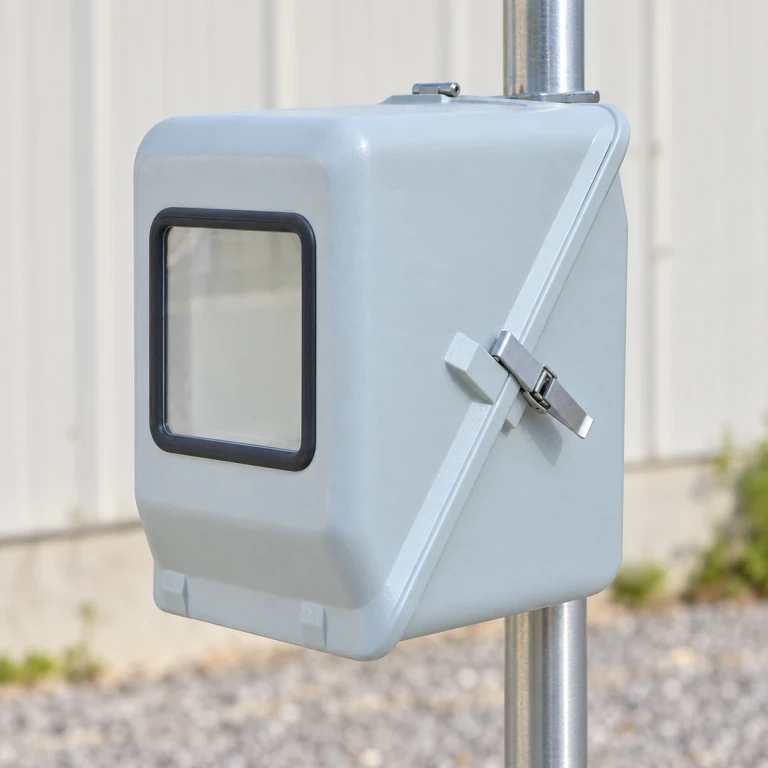
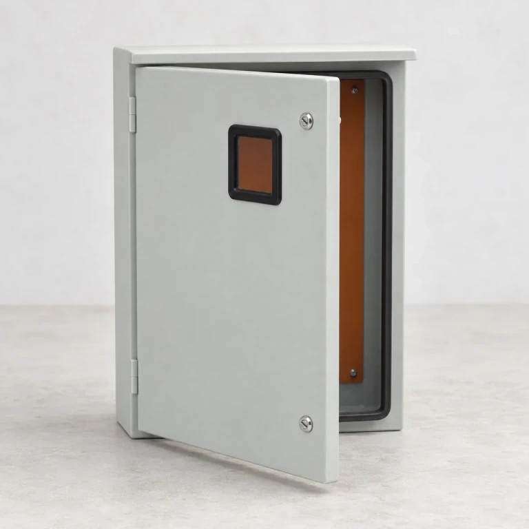
FRP Electrical Junction Box Shells
These empty fiberglass junction boxes house electrical terminations behind a hinged or screw-fixed cover. The body and lid have matching gasket seating edges. Cable-gland holes are machined to the selected fittings, while internal mounting lands or external flanges suit the terminal and support layout.
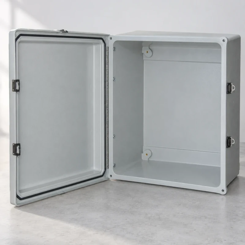
Empty enclosure volume, cover seal, hinge and backing-plate contacts.
Image credit: ·
Junction box options
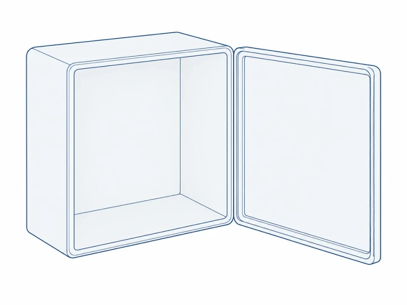
Hinged service cover
The hinged cover stays attached during inspection, so there is no separate lid to put aside.
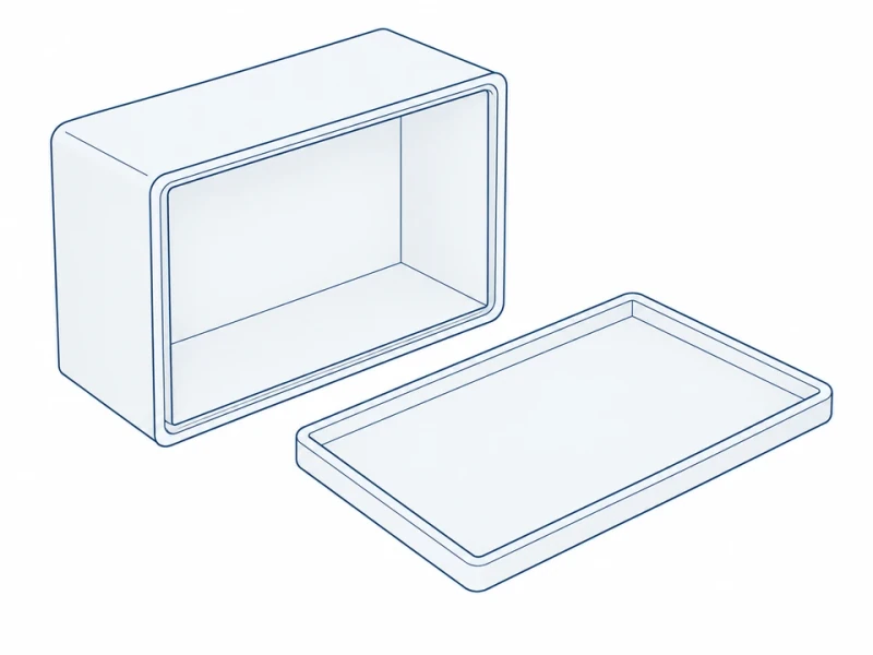
Lift-off screw cover
A screw-fixed cover lifts off completely, leaving the full front open for wiring.
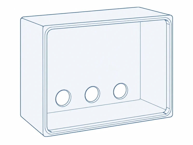
Cable-entry base
The enclosure body has cable-gland openings arranged around the internal terminal layout.
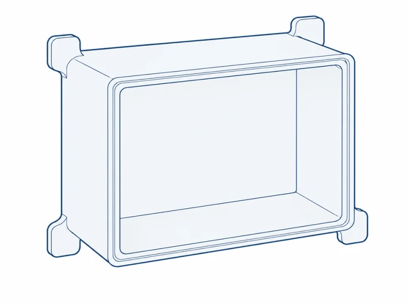
Mounting-flange body
External flanges carry the fixing points outside the box, keeping the interior free for wiring.
Junction box manufacturing
Body and cover molding
Bodies and lids are molded as matched pairs, with gasket seating edges and internal or external fixing areas where you need them.
Cable-entry machining
Gland holes are drilled to the selected gland sizes and positions, with finished contact edges.
Molded surface
Color and texture are consistent across box and cover, with finished edges around the mounting flanges.
Box size, cable entries and mounting
Interior and cable entry sizes
The front view shows the clear box opening’s width, a cable-entry diameter and the center spacing of two mounting holes in the rim. Usable wiring space also depends on the box depth, cover returns and backing plate.
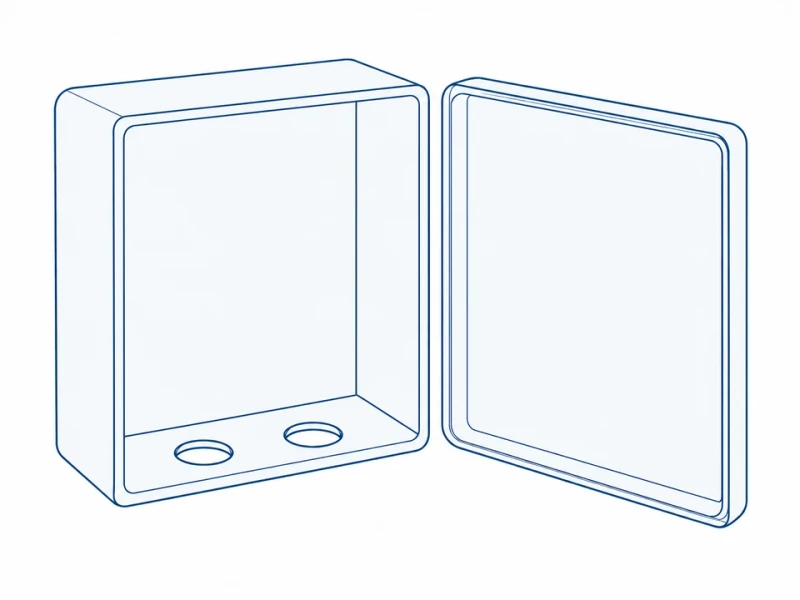
Separate cover and lower cable entries
The box depth, cover rim and lower cable holes are made to suit your backing plate and gland sizes.