Custom FRP Ophthalmic Device Housings
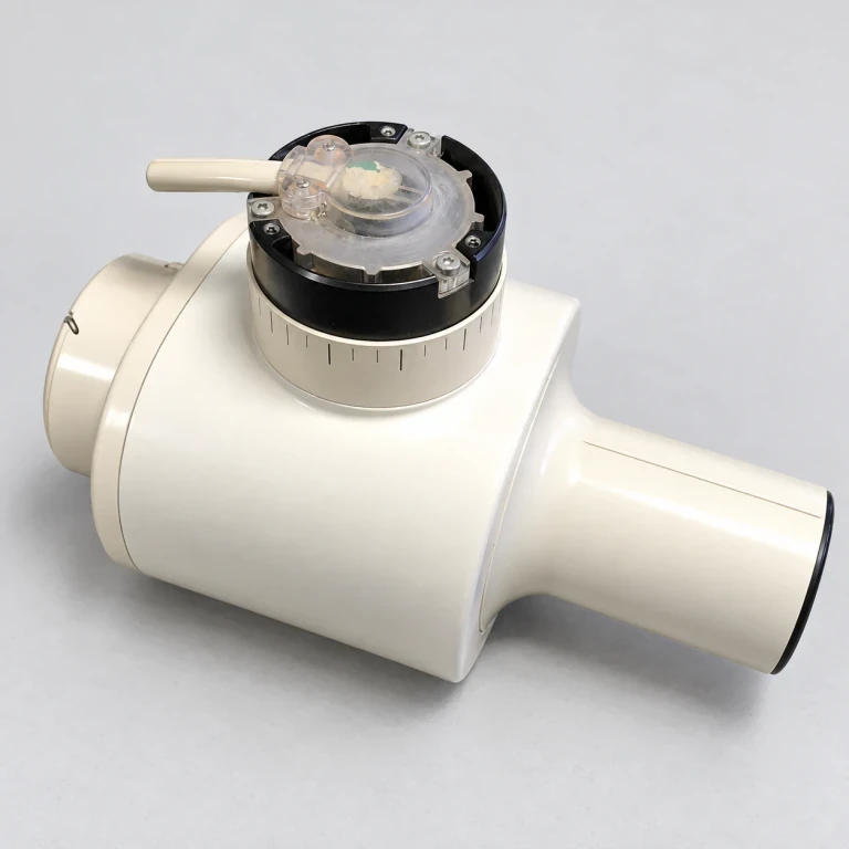
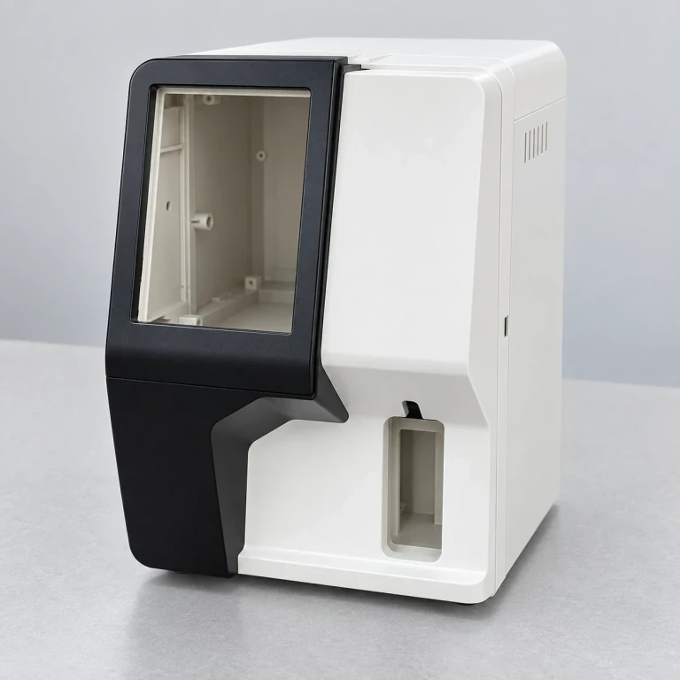
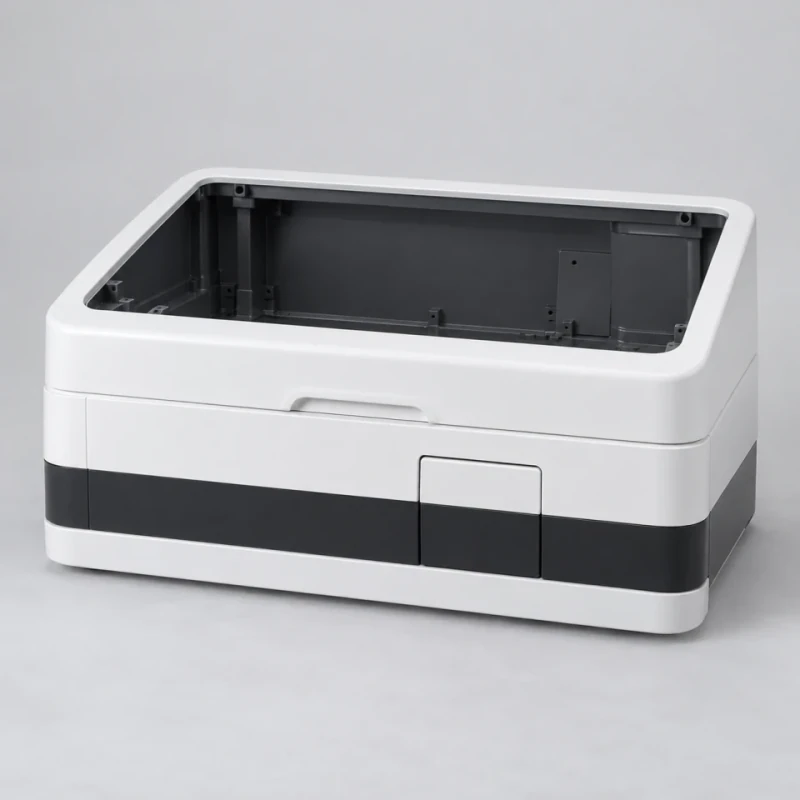
These fiberglass covers form the exterior of an ophthalmic instrument around its optics, display and base. Lens apertures, screen bezels, vented side panels and base cutouts can be shaped to the equipment layout. The optical assembly and patient-contact supports are not included.
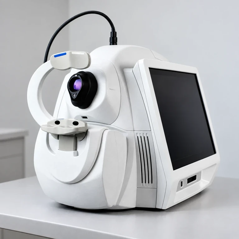
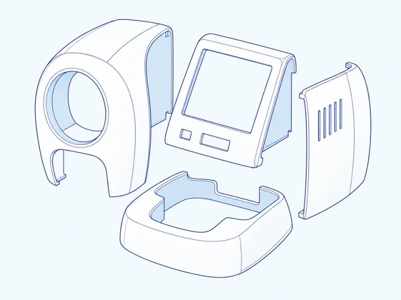
Instrument assembly reference for a rounded front shell, vented side cover and angled display bezel. We shape the exterior to your optical layout; lenses, display and patient-positioning hardware are separate.
Image credit: ·
Ophthalmic instrument covers
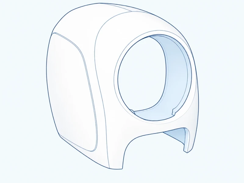
Optical front shroud
A rounded cover surrounds the optical opening, with lower reliefs for the positioning support.
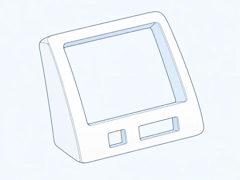
Angled display bezel
This inclined screen surround has lower connector openings.
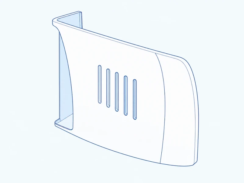
Ventilated side cover
Ventilation slots are cut into a side cover that can be removed separately.
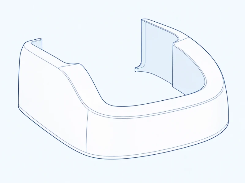
Lower base shroud
This rounded base shell has cutouts and fixing points for the positioning and mounting supports in your drawing.
Ophthalmic-cover customization
Instrument-cover molding
The rounded front contours, base curves and display slopes are formed to your optical-instrument model.
Lens and control cutouts
Lens, screen and connector openings are trimmed to match the selected optical and electronic modules.
Vented side covers and surface appearance
Vent slots and panel seams follow the internal layout, and color and gloss can be matched across the cover set.
Ophthalmic cover details
Optical front and lens opening
The front elevation shows the shell's overall width and height. The optical-opening diameter is measured across the circular lens aperture.
Bezel, vents and positioning relief
The angled display bezel has connector openings below the screen, the side panels carry vent slots, and the rounded base shroud is cut around the positioning supports.