A pool-slide package that meets at the joints.
We manufacture fiberglass slide bodies and coordinate the ladder, supports and fittings listed for your project. The slide route, joints and assembly package are reviewed together before delivery.
The chute route, outlet and support contacts follow the pool layout and are brought together during trial fitting.
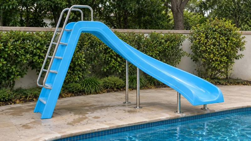
- We make
- Vacuum-infused slide bodies
- We coordinate
- Trial assembly
- You receive
- Agreed support package
Connect the entry, supports and receiving area.
A poolside slide has to connect several positions: the ladder on the deck, the entry at the top, the support points below and the outlet over the receiving water. The body shape alone does not settle those relationships. The pool plan gives the component package its starting point.
An entry and outlet fixed by the pool plan
Start height, route and receiving area need to follow the pool team’s layout.
Section joints along the riding surface
Adjoining chute pieces must meet along the agreed channel profile.
Ladder and support contacts
Mounting seats have to match the chosen ladder, supports and site connection details.
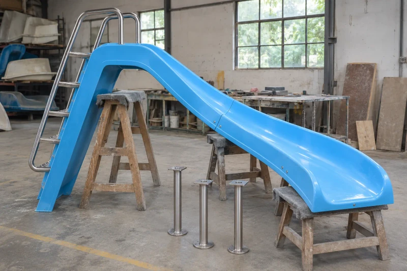
How we customize the parts.
Route and exit
Start height, chute width and outlet position follow your pool layout and the receiving area your pool team specifies.
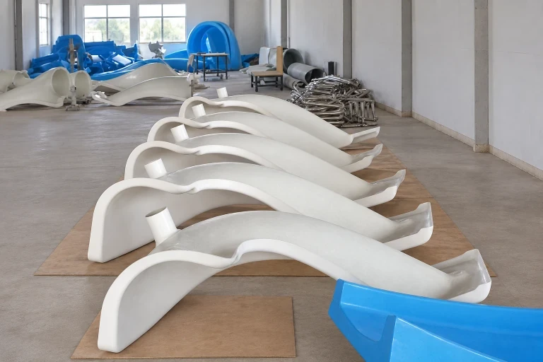
Riding surface and joints
The channel profile, section joints and trimmed edges are agreed together, and the trial assembly checks that the riding surface lines up at each joint.
Ladder and supports
Molded seats line up with the ladder, handrail and supports selected for the order. Deck anchors and water-feed connections follow your site requirements.
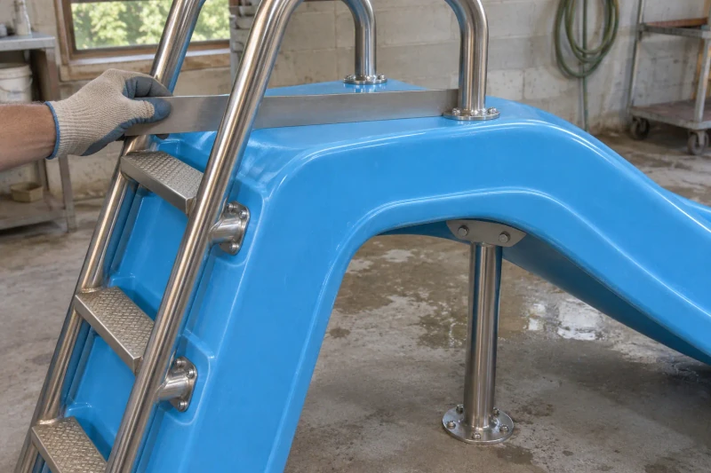
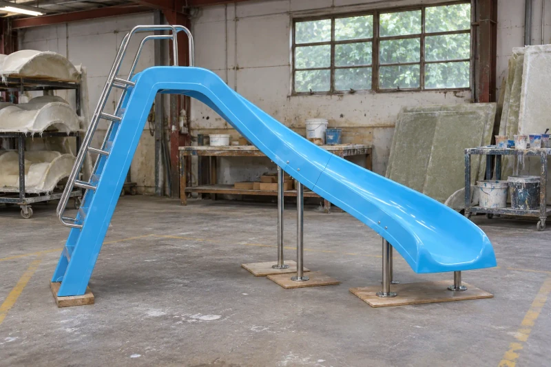
Mold and trial-fit
We mold and finish the slide bodies, then assemble the chute joints with the selected ladder and supports to check alignment and fit. Each part is labeled and packed with surface protection, and the shipment is planned around part sizes and access to your site.
Review the component fit before delivery.
Trial fitting brings the molded slide and selected fittings together before delivery. The installer receives a coordinated component arrangement with the section joints and support contacts already considered.
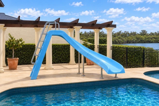
A shared assembly arrangement
Chute sections and selected fittings follow the same pool plan.
Joints reviewed before delivery
Trial fitting brings the channel edges and support contacts together.
A planned installation sequence
Component divisions reflect the route and access at the site.
Dimensions and design options
- Assembly
- Molded seats for the selected ladder and supports
- Surface appearance
- Custom color, with the riding-surface texture approved in advance
- Layout
- Start height, outlet and supports set from your pool drawing
Pool-slide body options
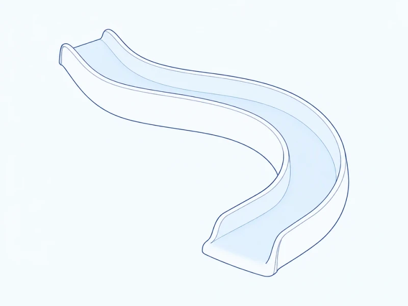
Compact curved body
A short curved slide has raised sides and a shaped pool-entry lip.
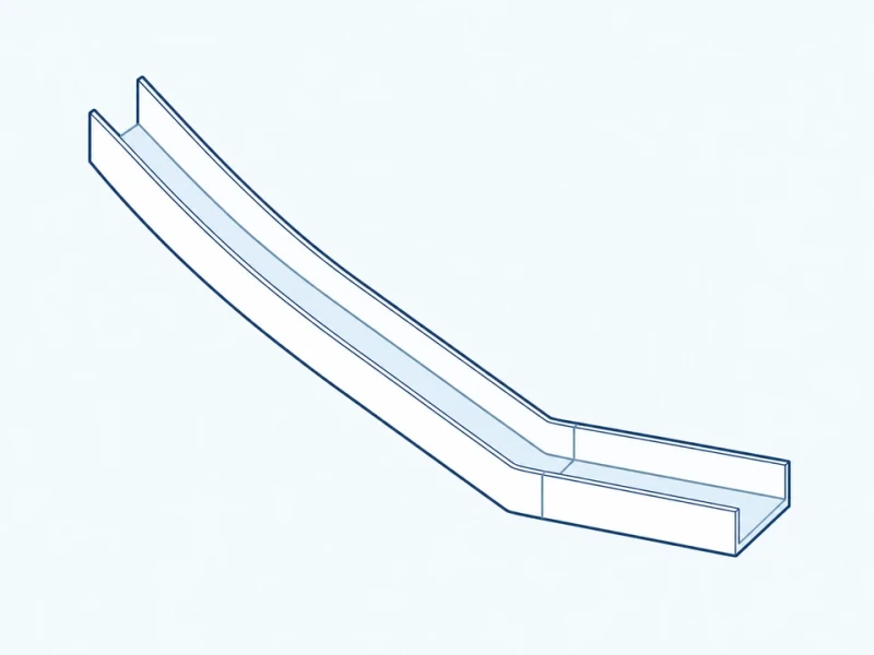
Straight channel
A straight molded chute ends in a level exit.
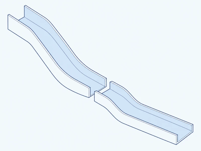
Split transport body
The body is molded in sections joined at an assembly flange, so a long slide can be shipped and handled in smaller pieces.
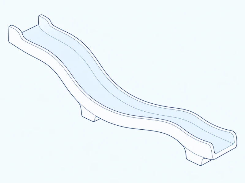
Body with support seats
Defined seats on the body locate the separate ladder and supports at agreed positions.
Poolside slide size and outlet reach
Body length, entry height and outlet overhang
The elevation measures the horizontal length of the body and the entry riding-surface height above the deck datum. Outlet overhang runs from the last support centerline to the end of the body. The receiving area, water level and complete slide installation remain part of the pool project design.
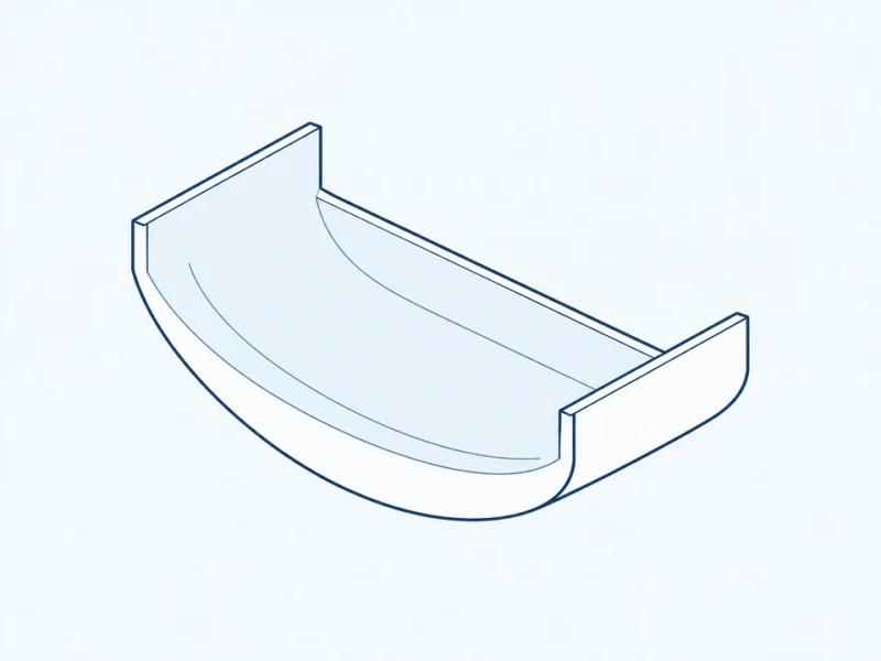
Molded channel and sidewalls
The open body is molded with a curved channel floor, raised sidewalls and the edge profile you choose.