See the coupe body at full size before tooling.
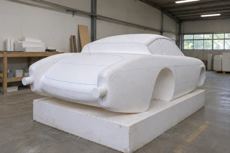
Turn your vehicle design into a full-size foam body master. We shape the model and mark key features so your team can review the body before committing to production molds.
A physical foam master brings the curves and opening positions into one reviewable reference.
- We make
- Full-size foam model
- We coordinate
- Body shape review
- You receive
- Preparation for molds
Review the whole body beyond the screen.
A coupe body needs to work as one shape. The bonnet, roof, wheel arches and rear body may look convincing on screen, but a full-size model gives the team a shared physical form to discuss. This service suits projects that need a body-shape review before mold development.
Curves that change at full scale
Roof, hood and body transitions need to be reviewed as one continuous vehicle form.
Openings located on the complete body
Lamp, door and glazing boundaries have to relate to the surrounding shape.
A reference for the tooling stage
The accepted physical form needs to carry the agreed profile changes into subsequent development.
How we customize the parts.
Body proportions
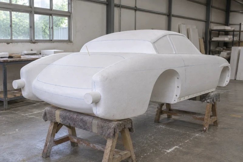
Overall length, roof profile, wheel arches and front-to-rear curves follow your vehicle design, so the proportions can be judged at full size.
Glass and lamp positions
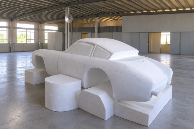
Window outlines and lamp placeholders, placed from your component drawings, show where these parts sit on the body.
Panel divisions
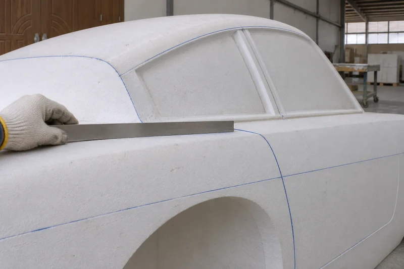
Marked edges and proposed gaps show where separate panels could meet, so part divisions can be discussed before the mold scope is fixed.
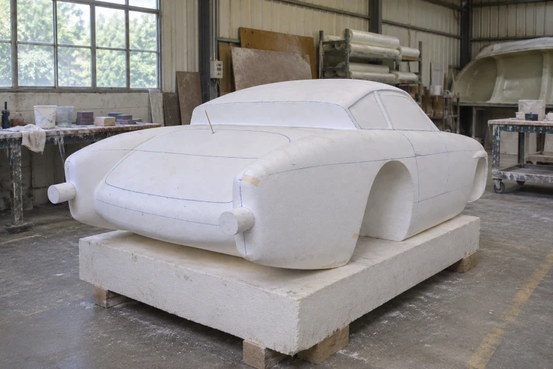
Shape the foam master
We shape the full-size foam form to the agreed design and add panel guides and component positions where they help the review. Your team reviews the form and we make the agreed changes. We then prepare the accepted master and the information needed to plan the mold stage.
Shape decisions made on a full-size reference.
The full-size master gives the vehicle team a common shape reference for reviews and agreed corrections. The next tooling stage can follow those physical decisions instead of separate interpretations of the exterior model.
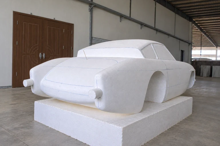
A shared full-size reference
The team can review complete body proportions on the physical form.
Changes located on the shape
Curves and opening positions can be discussed together.
A defined next tooling stage
Agreed profile decisions guide subsequent mold development.
Dimensions and design options
- Model
- Full-size foam master
- Review features
- Window areas, panel lines, lamp placeholders
- Next stage
- Master prepared for mold making
Choose the features needed for the body-shape review
A full-size foam master shows the roof, wheel arches and front-to-rear curves as one physical form. The review can cover overall proportions, panel lines, component positions or section checks.
Whole-body proportion model
The whole-body model lets your team review the long nose, rounded roof, rear shape and wheel-arch positions together. Solid window areas and foam supports keep the form available for inspection and agreed changes.
Panel-boundary review model
Marked door, cover and glazing boundaries show how the proposed panels sit on the side profile. The guide lines locate future divisions while the foam stays one continuous shape.
Window and lamp position reference
Solid window outlines and round lamp placeholders can be located from the component drawings. Your team can review these positions against the bonnet, fender crowns and roof before the next tooling stage.
Section-station review model
Station lines across the nose (A), cabin (B) and rear (C) mark where cross-section profiles are checked. The sections are review references; the master is not cut into parts.
Body envelope and model datum
The surface model locates the body envelope and components in a common coordinate system, with key review dimensions and a separate reference for the plane supporting the foam master.
- L / W · body envelope
- Nose-to-tail body length and maximum body width use the model coordinate system. Mirrors, lamp placeholders and other projections are identified separately to keep the measurement boundaries clear.
- H · roof from the agreed model plane
- Roof height is referenced to the agreed model datum. It is distinct from road clearance and from the height of a foam base or supporting fixture.
- Wheel, glass and lamp references
- Wheel-arch envelopes and glass and lamp positions follow the chassis and component drawings, with reference sections or check points for each area.
- Panel guides and review criteria
- Proposed panel edges, gap intent and the comparison method define the physical-model review. The review scope records which shape changes are included.
Locate the neighboring components and panel boundaries
The foam model lets the team review how the body, window outlines, lamp positions and proposed panel edges read together. The plan below marks those component positions alongside the outer form.
- A · glass outlines on the solid model
- The supplied glazing drawings locate the windshield, side-window and rear-window boundaries. The surrounding body transitions can be reviewed while these areas remain solid foam references.
- B · proposed panel divisions
- Intended edges and gap positions support the design review, while eventual part divisions and mold strategy follow the tooling brief. Guide lines on the master are not functioning panel joints.
- C · lamp positions and surrounding form
- Lamp placeholders follow the component references and their positions relative to the nose or rear body. Component-fit checks are defined separately from the visual shape review.
Record the accepted form before the tooling stage
- Physical shape review
- The review covers agreed views, sections and key points. Shape changes are recorded against the supplied design, with the accepted model revision kept identifiable.
- Master surface preparation
- The mold-making route determines the required master surface condition, including any finishing or sealing before mold work.
- Delivery and next-stage scope
- Broad foam surfaces are protected for delivery, and any transport divisions or supports are identified in advance.