A full-size reference for a changing interior curve.
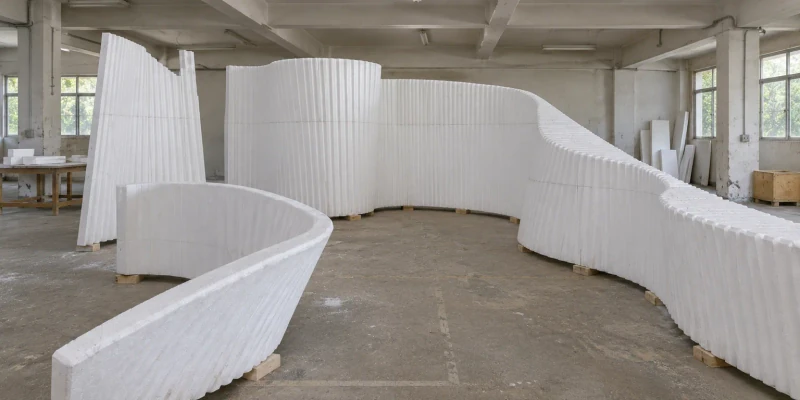
See a sweeping interior form at full size before developing the finished parts. We build foam profile masters that follow your plan curve, changing heights and architectural model.
Arranged foam profiles let the design team review height changes and transitions together before developing the final panels.
- We make
- Full-size foam profiles
- We coordinate
- Curves and changing heights
- You receive
- Review before final parts
Make a large curved feature easy to review.
A curved interior feature can rise, fall and change direction across a large area. Separate drawing sections explain individual positions, but a full-size profile arrangement lets the design team review those transitions together. It also gives the team a physical reference when discussing columns, ceiling clearances and adjacent spaces.
A curve changing in plan and height
Individual drawing sections need to read as one continuous spatial feature.
Each profile in the right position
The physical ribs must relate to the architectural drawing so changes can be located.
A master leading to final components
The accepted shape needs to inform later divisions, edges and support contacts without treating the foam as finished cladding.
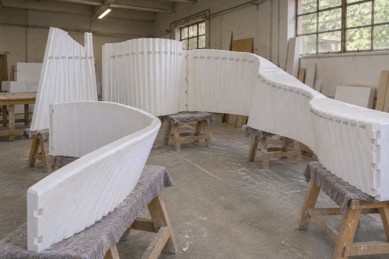
How we customize the parts.
Plan sweep and height changes
Individual full-size profiles follow the architectural model, showing how the shape changes around bends and between high and low sections.
Section positions
Numbered ribs relate the physical form back to the drawing, so a proposed change can be tied to the correct part of the curve.
The next decorative stage
Knowing whether the final feature will show separate ribs or a continuous surface helps plan later part divisions, edges and support contacts. The foam itself is a review model, not the finished panels.
Build and review the master
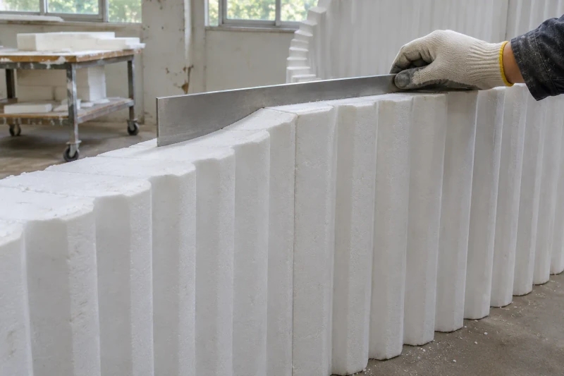
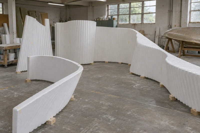
We cut the foam profiles and arrange them at full size, so your team can check the sweep, height changes and surrounding clearances on one physical model. We agree any profile changes and record the accepted form. That record becomes the starting point for sizing and dividing the finished components.
Agreed curves linked back to the drawing.
The arranged profiles make changing heights and transitions visible at full size. Tying the sections back to the drawing gives the design team a shared reference for agreed changes and final-panel development.
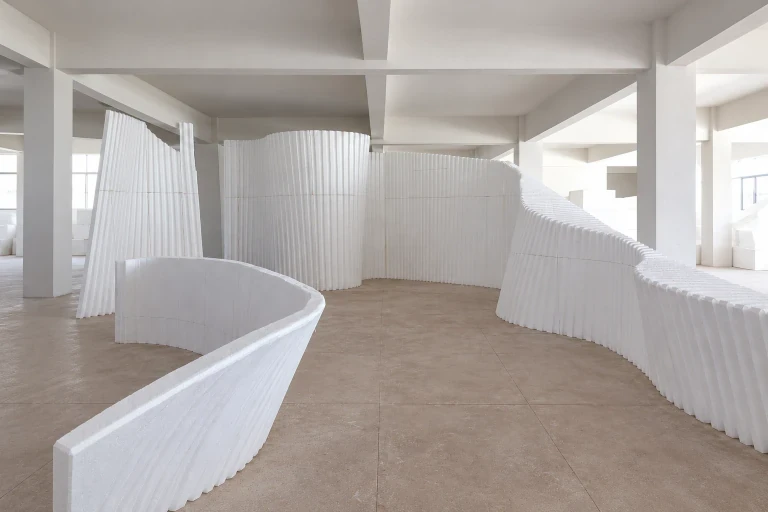
The complete transition visible
Full-size profiles bring changing heights and curves into one arrangement.
Changes tied to their location
Individual sections relate the physical master to the drawing.
A reference for final panels
The accepted curve guides subsequent divisions and component development.
Dimensions and design options
- Product
- Full-size foam profile masters
- Geometry
- Curves with changing heights
- Purpose
- Shape review before final parts
Full-size model arrangements
An entire sweep, a return or a few selected profiles can be modeled, depending on what needs to be checked. Shape changes can then be assessed at full size before final-panel tooling.
Sweep with changing heights
A continuous run of profiles shows how the top edge rises and falls along the plan curve. The whole transition and nearby clearances are checked against the architectural model before individual sections are adjusted.
Return and direction-change review
A plan arrangement shows how the profiles turn back through a tight part of the layout. Inner and outer curves, profile orientation and nearby clearances are set from the surveyed plan.
Grouped curved sections for fit review
Splitting a large curve into review groups makes it easier to handle and to relate to the site drawing. Matching section references at the group boundaries let position and height be checked when the groups are set side by side.
Individual profile and datum checks
Selected profiles can be checked one at a time before the full arrangement is accepted. Each one relates to its drawing station and the shared height datum; A–D mark different profiles, each with its own height and side contour.
Profile positions and heights
A free-form sweep needs a station schedule as well as the overall model. Each profile is located on the plan and given its own shape and height from a common datum. The example locates station B by plan offsets, with its height shown in a separate section.
- X / Y · station location on the plan
- Each numbered profile has a position measured from a shared plan origin. The sketch uses right-angle offsets to locate B; overall span and distance along the curve remain separate measurements.
- H · height at the selected profile
- The top of each profile is measured from the shared Z0 plane. A height schedule links each rise or fall to the correct position along the sweep.
- Individual section shapes and intervals
- The surface model and station schedule set each profile's outline, orientation and spacing. The curve need not have a constant radius or equally spaced ribs.
- Survey and handling references
- Surveyed columns, ceiling limits and access routes establish the clearance and handling limits. Marked reference points can be compared with the physical arrangement.
Drawing references and site clearances
Numbered sections make a shape change traceable to its position on the curve. This sketch isolates four selected profiles so their identity, the nearby site envelope and a possible grouping boundary remain easy to discuss during review.
- 01–04 · numbered profile references
- Each physical section is linked to the drawing schedule and kept in a recognizable orientation. Accepted changes are recorded against the individual profile and the shared plan and height datums.
- A · surrounding structure and clearances
- The survey records the column, ceiling and adjacent-space boundaries. The sweep is checked against these measurements using clearance criteria agreed with the architectural team.
- B · proposed grouping boundary
- The accepted form is used to discuss handling groups, future part divisions and edge continuity. This line is a planning reference only; finished joints and support contacts are set in the next design stage.
From reviewed model to finished components
- Form and transition review
- The full-size review checks the plan sweep, height changes and transitions between profiles at the agreed stations. Accepted revisions are recorded before the finished components are developed.
- Intended finished appearance
- The finished feature may expose separate ribs or form a continuous surface. That choice informs the next-stage panel layout, edges and support coordination.
- Master record and supply scope
- The review leaves a record of the accepted profiles, their positions and any changes. That record supports a separate quotation for the finished decorative parts.