FRP Air Compressor Covers
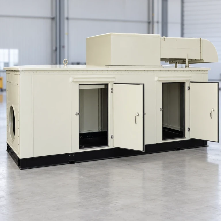
An FRP casing forms the outer body of an air-compressor package, with doors or lift-off sections arranged around maintenance access. The shell, louvers, control openings and pipe passages are made to the machine layout and the compressor supplier's cooling design.
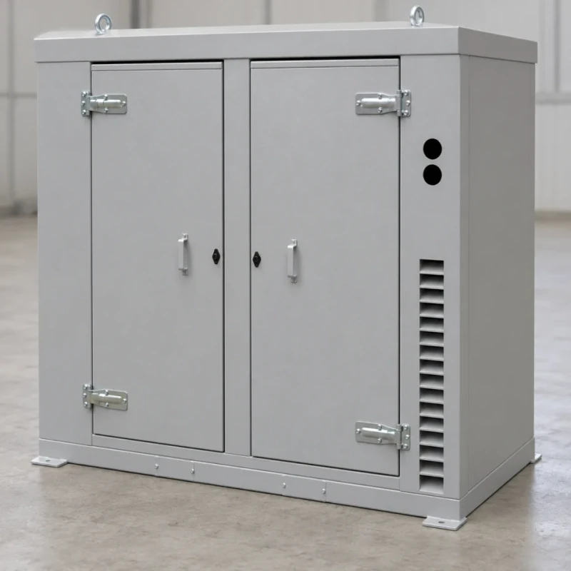
Service doors, empty control apertures, cooling-air louvers and lifting contacts.
Image credit: ·
Compressor casing options
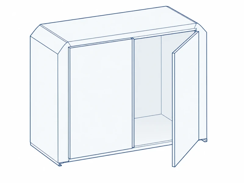
Twin-door casing
Two front doors open wide for routine filter, oil and cooler service.
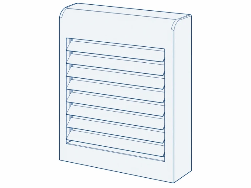
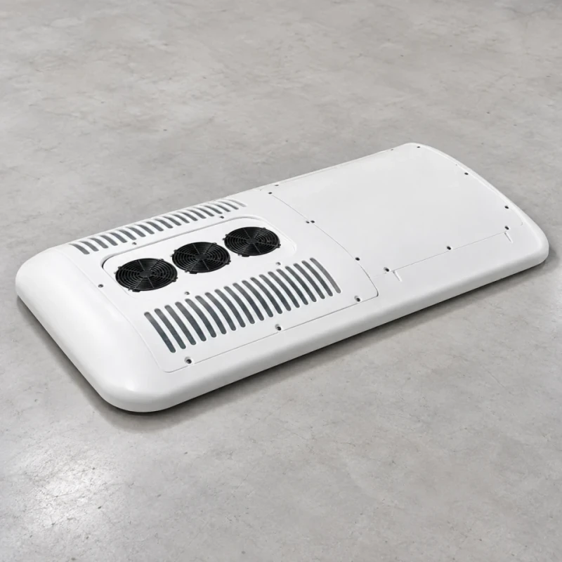
Louvered panel
A louvered panel is placed at the package's cooling-air intake or hot-air outlet.
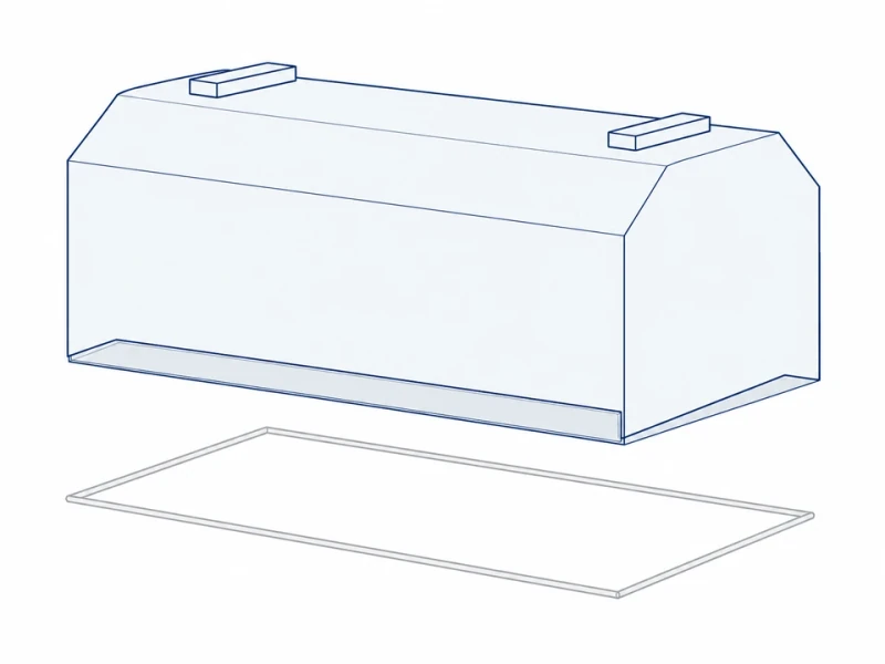
Lift-off hood
A hood lifts off for top access to the compressor.
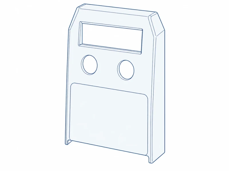
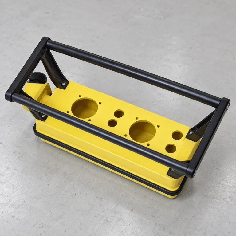
Control panel
The removable control face has display and instrument cutouts.
Compressor casing customization
Casing molding
The casing sections are molded with local reinforcement at the frame and door fixings.
Panel trimming
Louvers, control cutouts and pipe passages are cut to the compressor supplier’s cooling and service layout.
Surface appearance and lining areas
We apply gelcoat in the chosen color and gloss and prepare mounting areas for the specified acoustic lining.
Service access, airflow and lifting points
Door, vent and lifting layout
Service-opening width, vent height and cover lift-eye spacing follow the compressor layout. The lifting details refer to the cover; handling the complete machine requires a separate lifting design.
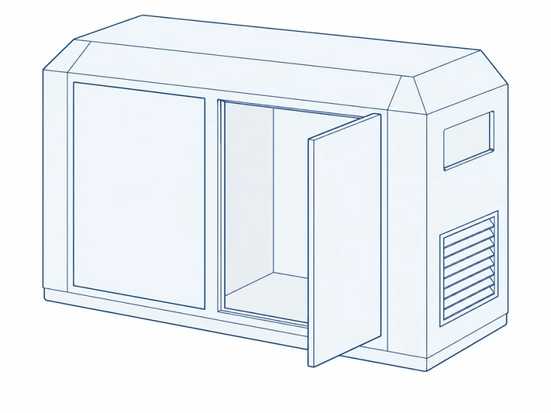
Front door and side louvers
Front doors, side louvers and upper side openings are positioned to the compressor supplier's layout.