FRP HVAC Equipment Covers
Fiberglass HVAC covers form the exterior roof and service casing around an equipment unit. Fan apertures, removable panels and fixing areas for separate guards can be arranged to suit its airflow and maintenance layout.
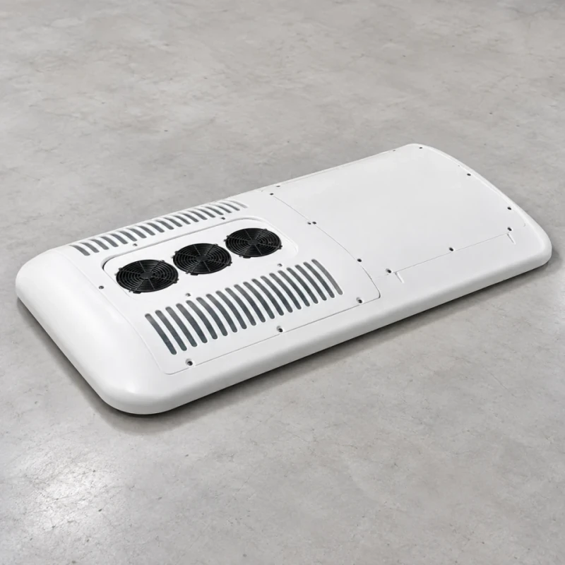
HVAC cover perimeter, service panels and airflow opening interfaces.
Image credit: ·
HVAC cover options
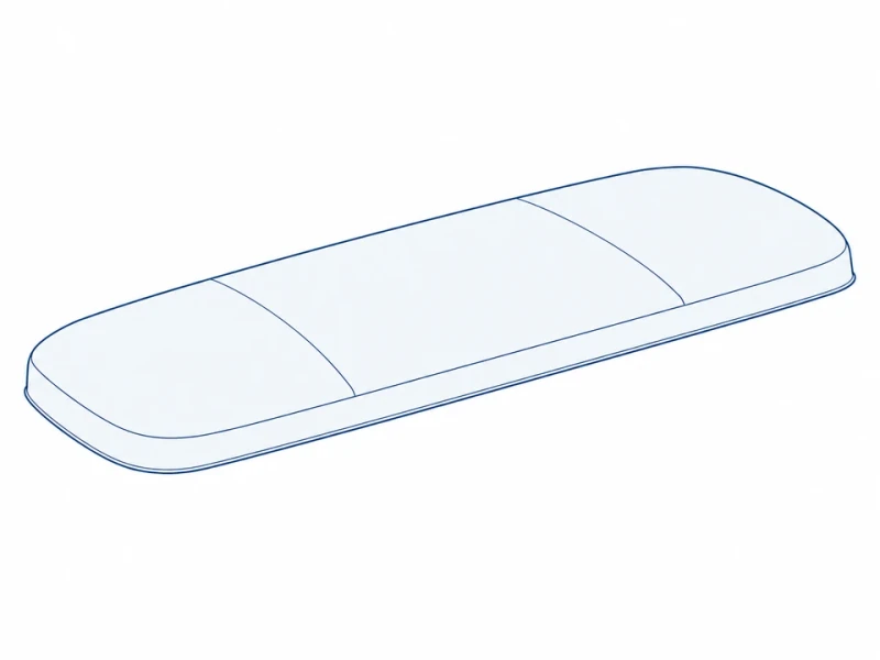
Low-profile roof cover
A low-profile molded top follows the equipment height and fixes down along the perimeter.
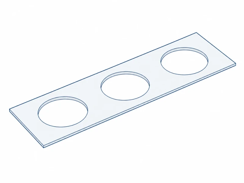
Fan-opening section
A removable top panel has fan openings and fixing areas for separately specified guards.
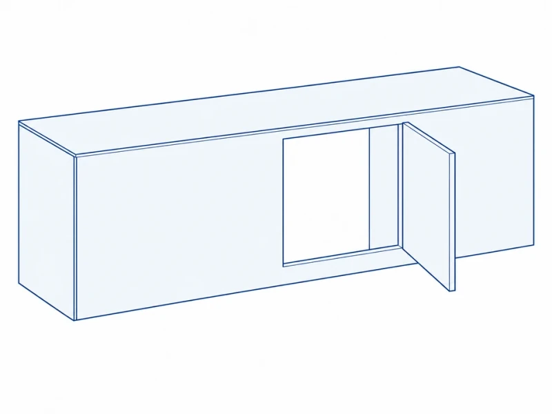
Side service shroud
A side service opening gives access to filters and components.
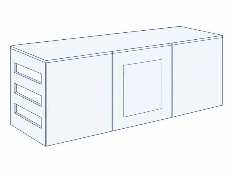
Sectional enclosure
Joined cover sections divide a larger enclosure into smaller panels for handling and service.
HVAC cover construction
Panels and returns
Roof and service panels are molded to the unit profile, with reinforced perimeter and joint areas.
Fan and service openings
Fan openings, guard fixing areas and removable panel edges are prepared to your equipment and filter layout.
Edges and paint
Drainage and mounting edges are finished before the sections receive the specified color, gloss and texture.
HVAC top and fan spacing
Cover length and fan spacing
The top plan measures overall cover length, clear fan-opening diameter and spacing between two adjacent fan centers. Opening size and spacing follow the equipment layout; cooling capacity, air resistance and noise depend on the complete HVAC system.
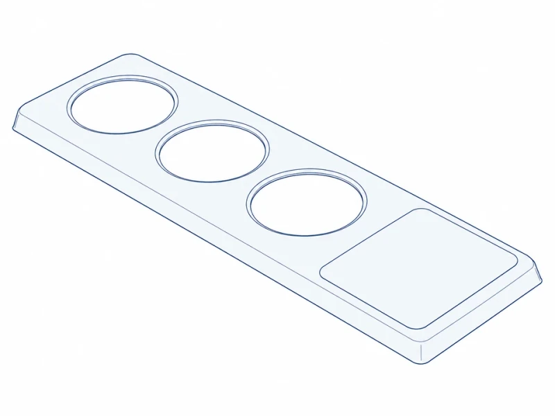
Fan rings and service panel
Raised fan rings, a local service panel and low perimeter returns form the top cover. Fans, compressors and guards are separate components with their own specified attachments.