A fan housing that fits the rotor, guard and frame.
Custom fiberglass fan casings with a flared inlet, rear body and prepared fixing areas matched to your rotating parts and support arrangement.
The inlet profile and mounting areas follow the fan assembly, with access for removing the guard.
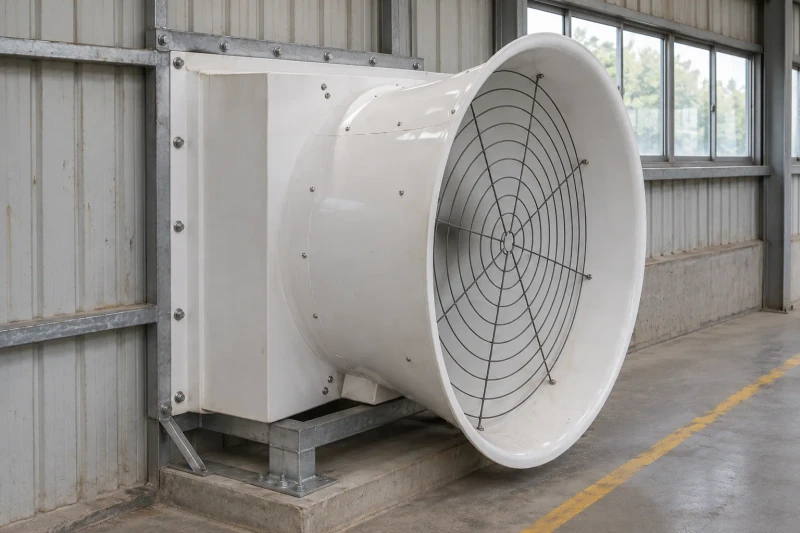
- Process
- Compression molding
- Component
- Flared inlet and rear casing
- Fit reference
- Fit to your fan drawing
Resolve the airflow shape and the assembly interfaces.
For a ventilation fan, the inlet mouth, casing depth and rear mounting arrangement must fit around the selected rotating equipment. The guard also needs its own attachment points and a practical route for removal during servicing.
An inlet leading into the casing
The flared mouth and casing depth must follow the fan designer’s section.
Rotor clearance and rear supports
The shell needs to fit the specified rotating equipment and meet the support frame at the rear.
A guard that can come off
Guard attachment and removal access have to work without moving the entire housing.
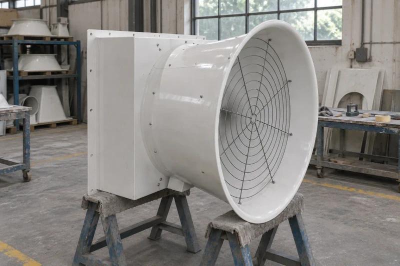
How we customize the parts.
The flared inlet and transition
The inlet follows the section from your fan designer and runs into the casing at the required depth. Matched tooling forms both the inner and outer surfaces.
Space for the rotor
The casing outline follows the rotor size and clearances in your assembly drawing. Rear fixing areas line up with your support structure.
Removable guard fixing
The inlet rim and guard fixing points are laid out together, so the guard can come off for inspection while the housing stays in place. Edge preparation follows the guard you choose.
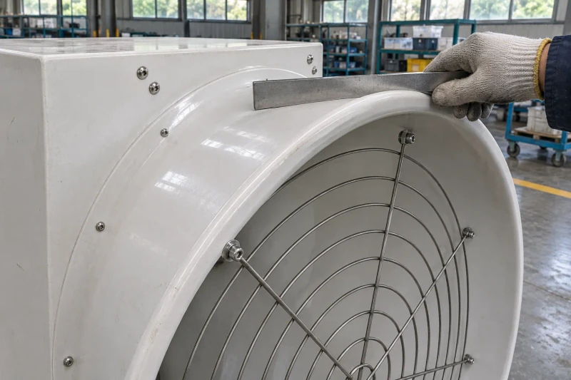
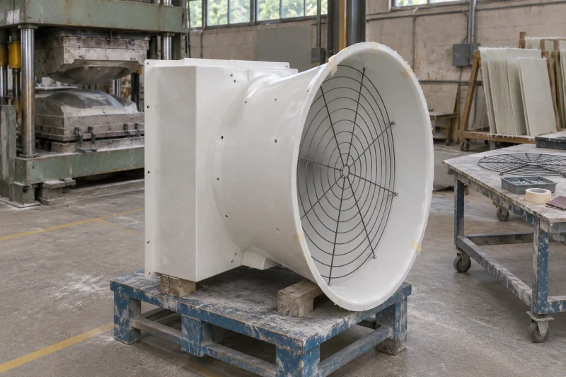
Compression-mold and trim the body
Fiberglass sheet material is pressed in heated matched tooling. We then trim the edges and prepare the specified guard and mounting holes. The first housing is checked on your reference fan assembly. Batch parts follow the accepted dimensions and fixing details.
A casing developed with its connections.
The casing and guard can be reviewed against the same fan assembly. Shared mounting and clearance references help the equipment team settle the interfaces before repeating the molded housings.
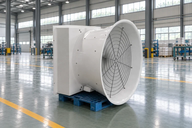
Coordinated casing interfaces
Inlet depth, rotor space and rear mounting follow one assembly drawing.
Guard removal retained
The fixing layout leaves a planned route for inspection access.
A physical fit reference
The first housing lets the equipment team review the selected connections.
Dimensions and design options
- Product family
- FRP Industrial Fan Housings
- Production basis
- Approved drawing or sample
- Example configuration
- Round inlet, square backplate, guard fixing points
- Dimensions
- Made to your fan assembly drawing
- Performance
- Airflow and fan performance set by the equipment OEM
Fan inlet cowling options
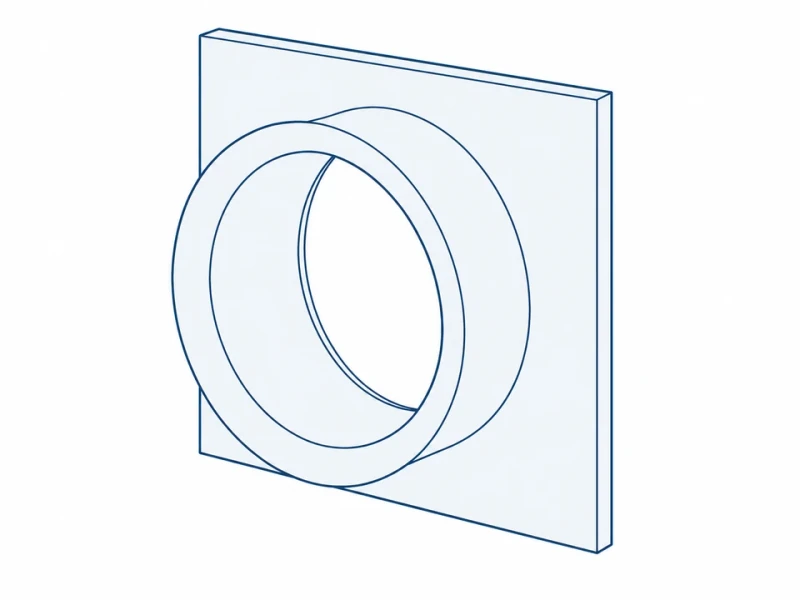
Round inlet and plate
A projecting round inlet meets a flat square backplate with corner fixing areas for the fan frame.
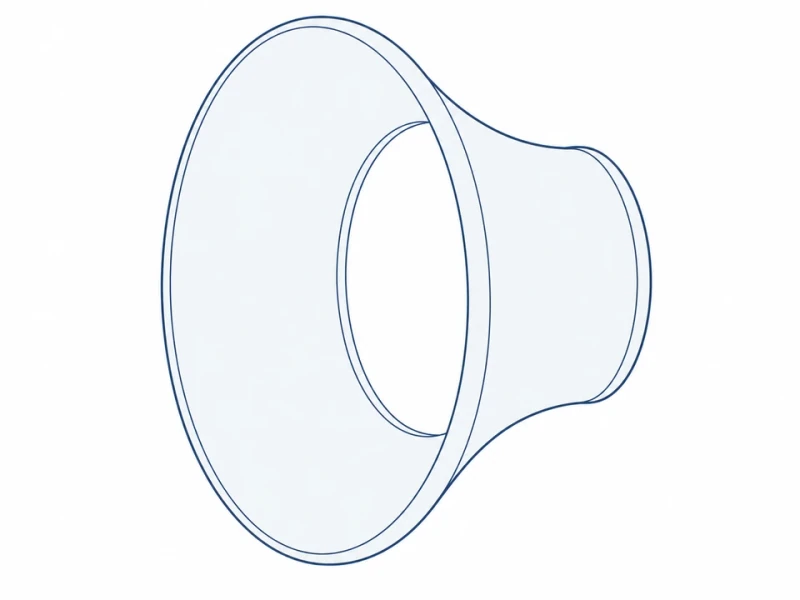
Flared inlet bell
A wider flared bell follows the inlet profile specified by your fan designer.
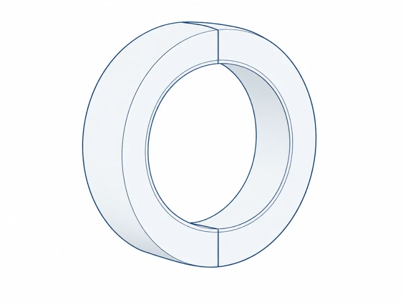
Split ring
Two half-ring sections join around an installed fan where a one-piece ring cannot be fitted or removed for maintenance.
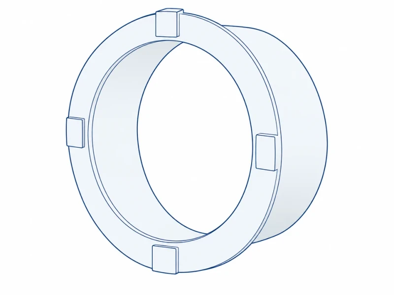
Grille-ready front rim
A formed front rim provides fixing points for a separately specified protective grille.
Inlet and backplate sized to your fan
Inlet ring and backplate sizes
The front elevation measures backplate width and fixing pitch between the two upper hole centers. D marks the clear inlet diameter. These dimensions follow the fan assembly drawing.
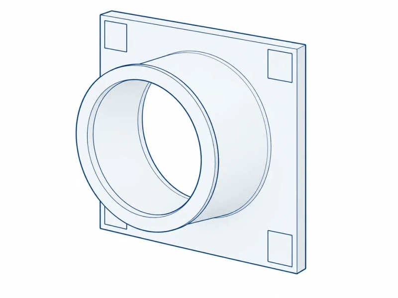
Projecting round inlet
Inlet projection and rim radius follow your profile, on a square plate with four corner fixing areas matched to the fan frame.