Split shells that follow the cable route.
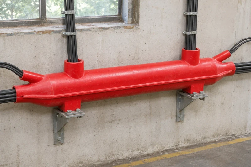
Custom conduit halves that close around a cable bundle, with branch collars, end openings and joining edges made for your route.
The main body opens around the cable bundle, with joining access and branch-end fitting considered before molding.
- We make
- Two molded half-shells
- We coordinate
- Hand-laid glass reinforcement
- You receive
- Custom branches and joins
Resolve the cable space and the fitting sequence.
A cable route with branch connections needs more than a straight tube. The enclosure must follow the bundle, leave space at the exits and separate into parts that your installation team can handle around the cables.
A cable bundle with several exits
The shell needs clearance around the main bundle and alignment with the branch positions.
Joining the halves around the route
The split line must leave edges and fasteners reachable during installation.
Closed collars at the branch ends
These collars need cable-end access or fitting before the branches are connected.
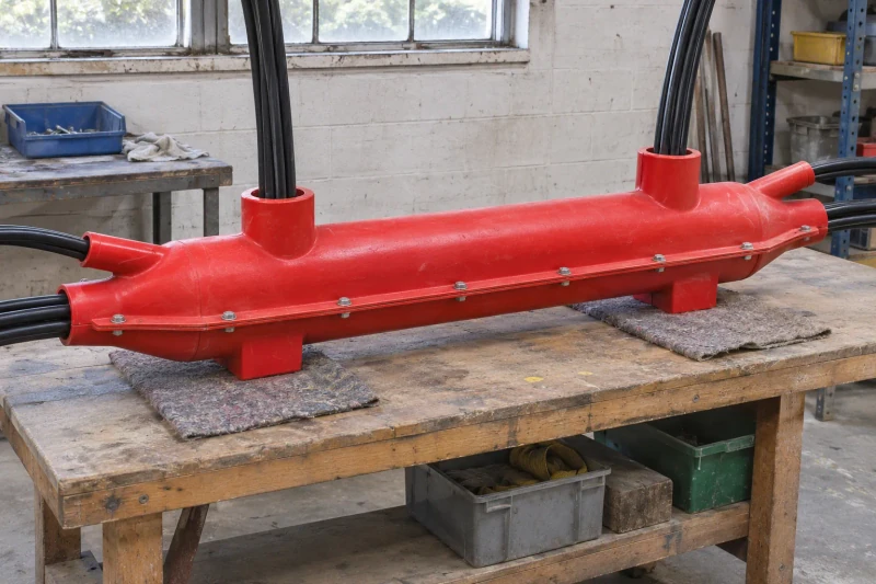
How we customize the parts.
Space inside the shell
The internal profile follows your cable bundle and required clearance, and the end shapes and branch collars line up with where the cables enter and leave.
A practical split line
The main body halves meet along prepared joining edges, with fixings where installers can reach them. Closed branch collars are fitted using the cable-end access and assembly sequence established for the route.
Reinforced curves and edges
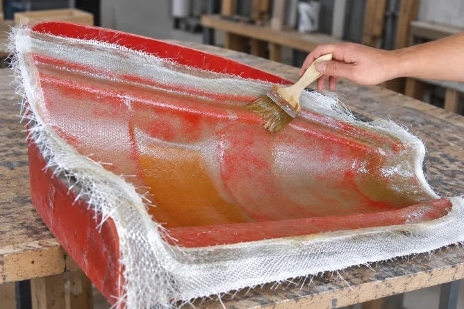
Glass reinforcement is laid into the curved molds and the joining areas. The laminate is built for the exposure and handling you specify.
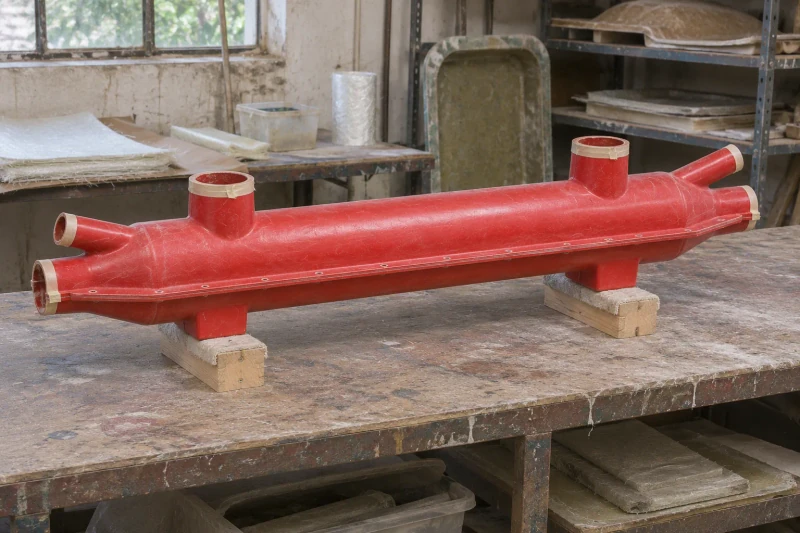
Mold and trim the sections
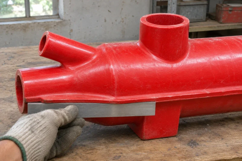
We hand-lay the fiberglass shells, form the branch details and trim the mating edges. Fixing positions are prepared from the assembly drawing. A sample assembly lets your team check cable space and joining access. Production sections are then checked and packed with the collars and edges protected.
The route and assembly method considered together.
The main split body can be arranged around the cable bundle using prepared joining edges. The defined branch-end access and fitting sequence help the installation team plan the closed collars before connecting the branches.
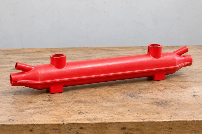
The main body opens around the bundle
Two half-shells follow the provided cable envelope.
Joining edges remain reachable
The split and fixings reflect the planned installation sequence.
Branch fitting planned explicitly
Closed collars use the agreed cable-end access before branch connections are completed.
Dimensions and design options
- Construction
- Two molded half-shells
- Laminate
- Hand-laid glass reinforcement
- Custom features
- Branch collars, reduced ends, joining edges
Split-shell forms and branch arrangements
The split body encloses the main cable run, while upright or angled collars follow branch cables. The collars shown are closed tubes, so fitting them requires branch-end access or installation before the branch is connected. Reduced ends and prepared mating edges complete the shell arrangement.
Straight split enclosure
Two curved shells close around a straight cable run, with clear bore, length and joining edges sized for the route and the space needed to bring the halves into position.
Two upright branch collars
Upright collars guide cables where they leave the main run. Each collar’s height, opening and position follow the route; the closed collar needs access to a cable end or installation before the branch is connected.
Reduced ends with an angled outlet
A tapered end narrows the opening where the bundle gets smaller or exits, and an angled branch follows the cable direction. Transition and opening edges are defined as separate sections on the drawing.
Separately supplied matching half-shells
Upper and lower shells can be supplied separately for fitting around the main cable run. Mating-edge width, assembly direction and fixing preparation determine how the body halves join; any closed branch collars also need a workable cable-end access route. The shells do not assume a particular clamp or fastener.
Locate the branches from a defined end datum
The route drawing and cable-bundle cross-section define the shell envelope. Measuring every branch from the same end keeps the shell openings in line with the cables.
- L · overall length and section divisions
- Overall length includes tapered ends and the positions where adjacent sections meet, within the maximum piece length that can reach the installation area.
- D · internal cable clearance
- Clear bore allows space around the cable bundle for installation and any change at the exits. Wall thickness is agreed separately.
- X · branch location from the end datum
- Each branch center is located from the same end, with its opening size, collar height and angle defined separately. The sketch marks only the first upright branch.
- Split edges and end transitions
- The joint layout defines mating-edge width, any gap or overlap, reduced-end sections and the order in which the halves go together.
Close the halves around the cable envelope
The end section shows how the halves close around the cables. The dashed circles mark the cable envelope and the dashed ledge a support position; fasteners, seals and supports are defined for each project.
- A · longitudinal mating edges
- The curved halves meet along defined edge widths, with access to the fasteners. Any hardware, gasket or closure test is listed separately, and the drawing does not imply a seal rating.
- B · cable and assembly space
- The main cable envelope and assembly clearance determine how the two body halves come together. Branch direction and end access govern how the closed collars are fitted.
- C · support contact
- Support contact positions account for loads and clearance from the joining edges. Any support parts we supply are itemized in the quotation.
Shell construction and exposed edges
- Curved shell and joining areas
- Glass reinforcement is laid into the curved form and the mating edges, with the laminate built for the exposure, handling and supports you specify.
- Cable exits and visible surfaces
- Edges are trimmed and finished around the bore, branches and split lines, in the exterior color you choose. Cable clearance at these edges is checked on the sample assembly.
- Checks and protected delivery
- We check the bore, branch positions and mating edges, plus any protection tests you require. The shells are supported in the packing, with the collars and thin edges protected.