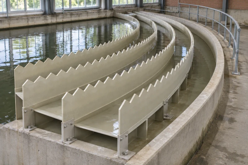
Basin modules that share one crest and fixing reference.
Custom notched plates and open collection channels, with curves, crest profiles and joints made to the process design.
Curved channels, notched plates and support contacts follow the process layout together.
- We make
- Weir plates and launder sections
- We coordinate
- Serrated upper edges
- You receive
- Basin support coordination
Coordinate the basin curve, upper edges and supports.
A treatment basin can combine weir plates and collection channels in straight and curved runs. Their crest levels, sections and fixing positions follow the process design, while the individual pieces must suit access for installation and later cleaning.
Straight and curved basin runs
Channels and plates need section lengths that follow the basin geometry and handling limits.
Notched crests at an agreed level
Upper-edge positions must follow the process engineer’s hydraulic drawing across adjoining pieces.
Supports with cleaning access
Fixing areas and removable sections need to work with the basin frame and maintenance plan.
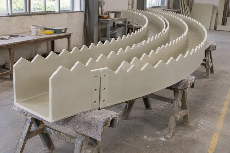
How we customize the parts.
Section shape and curvature
Curved channels and compartment sections follow the basin dimensions. Module lengths and joints are divided around the access and handling limits supplied for the site.
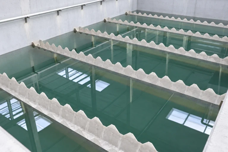
Notched crests and levels
Notch pitch, depth and crest elevation follow the process engineer's hydraulic design. Repeated plates and adjoining sections use the same agreed crest reference.
Supports and removable sections
Attachment areas follow the support frame and fixing schedule. Where removable modules are specified, their edges and fixing access are included in the manufacturing detail.
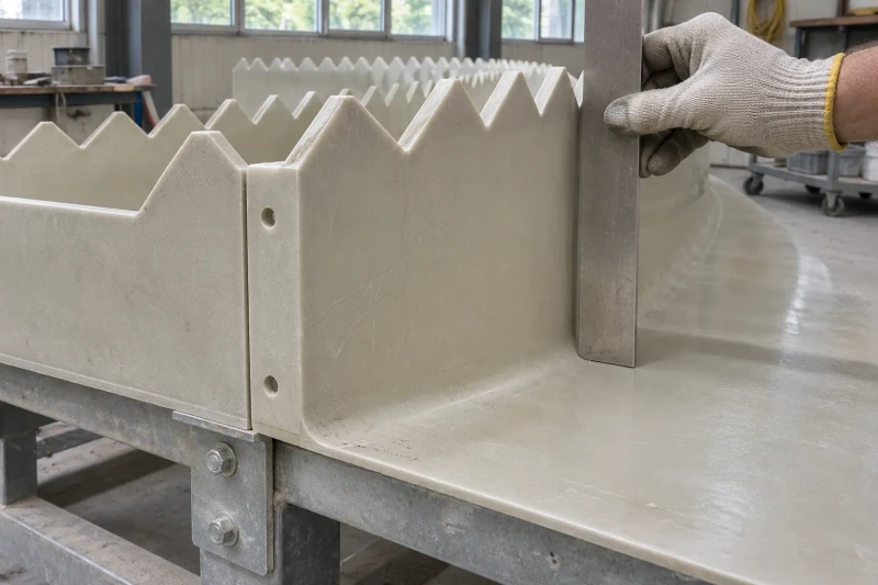
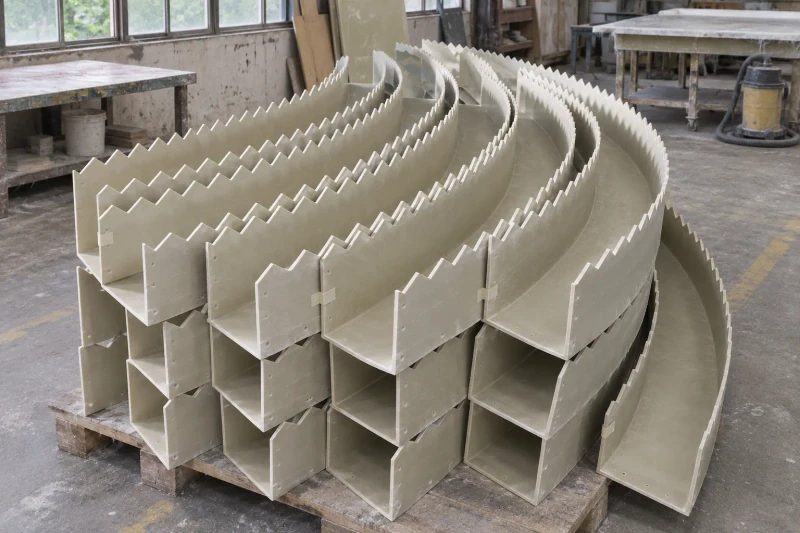
Form and prepare the sections
The fiberglass parts are made to the selected profiles and construction. Serrated edges, joints and fixing preparations follow the released module drawings. Dimensions and edge positions are checked against the order requirements. Modules are marked by layout position and packed with their upper edges separated and protected.
Prepared sections with planned cleaning access.
The modules share the process engineer’s crest and fixing references. Planned section lengths and removable areas let the installation team coordinate the basin assembly and retain the specified cleaning access.
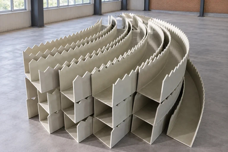
One crest reference across sections
Notched upper edges follow the process engineer’s drawing.
Modules sized for handling
Section lengths and joints reflect basin access limits.
Cleaning access considered
Removable areas and fixing positions follow the maintenance arrangement.
Dimensions and design options
- Product
- V-notch plates and launder sections
- Upper edge
- Crest profile to the hydraulic design
- Supports
- Fixing areas matched to your frame
Weir plates and collection-channel sections
V-notched weir plates and open launder channels serve different parts of a basin's collection layout. We manufacture the crest profile, channel section and joints to the process design. Scum baffles are separate components with their own position and edge detail.
Curved open-channel module
Two curved sides and a connecting base form an open channel. The radius, channel width and serrated edge follow the basin section and operating-level drawings.
Straight V-notch weir plate
A flat plate carries the specified overflow crest along a straight run. Notch spacing, notch depth, crest elevation and support positions follow the process engineer's drawing.
Segmented curved run
Shorter curved modules form a longer run where access limits handling length. Joint positions and edge alignment are agreed so the assembled run follows the specified radius and level.
Removable short-span section
A shorter module can be lifted from agreed bearing locations for cleaning. The removal direction, fixing access and clear space are coordinated with the basin support drawing.
Module span, height and curved profile
The elevation defines overall span, wall height and crest level, while the basin plan establishes curved runs. Notch pitch, notch depth and termination details follow the process drawing.
- L · span and module division
- End-to-end length, compartment positions and joint locations define each module, within the handling size and access route into the basin.
- H · wall height and crest level
- H marks the plate or channel-wall height. The basin datum sets the crest elevation; the launder's clear width and base section are specified separately on its cross-section.
- R · curved-run geometry
- The radius reference and segment angle define the curved geometry. This sketch marks the outer-face radius; a basin schedule may instead use the inside face or centerline.
- Weir crest and notch detail
- Notch pitch, depth, end details and crest-elevation checks follow the process engineer's hydraulic design.
Bearing, joint and removal details
The support arrangement is part of the basin design. The reference sketch separates the molded section from the bearing and adjacent module so each contact can be specified before manufacture.
- A · bearing contact
- Bearing width, support spacing and attachment areas follow the basin support layout. Support members and fasteners are included only when itemized in the order.
- B · module joint
- The joint detail sets the gap or overlap, edge-level alignment and fixing access. Sealing requirements are defined separately where the process calls for them.
- C · removal space
- The removal layout shows the lift direction and clearances above and beside removable sections, including access to the specified fasteners.
Match the construction to the water and cleaning duty
- Resin and laminate
- Water chemistry, temperature, cleaning agents and unsupported spans inform the agreed resin and fiberglass construction.
- Cut edges and working faces
- Edge finishing and exposed-face requirements cover the serrations, module ends and prepared fixing areas.
- Inspection and packing
- Inspection covers the agreed radius, section, edge-level and support checks. Packing separators protect the serrated edges and preserve the module shape.