A forklift cover that clears the machine beneath it.
Custom fiberglass covers with a raised center, returned side edges and prepared fixing points, finished in the gelcoat color your equipment needs.
The raised crown, perimeter trim and reinforced fixing areas follow the machine and its removal route.
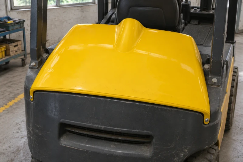
- Component
- Molded fiberglass cover, gelcoat face
- Fit
- Made to your machine layout
- Project size
- Reference: 820 × 580 × 150 mm
Match the outer face to the equipment underneath.
A forklift cover has to follow the equipment beneath it as well as the exterior appearance. Its raised center provides the specified space over the machine, while the perimeter and mounting points need to match the surrounding bodywork.
Clearance beneath the raised crown
The large molded face has to cover the equipment while clearing the components beneath it.
Fixings reachable on the machine
Mounting positions need reinforcement and space for a technician to reach the fasteners.
A perimeter that can lift away
The cover edge must match the surrounding bodywork and the planned service-removal direction.
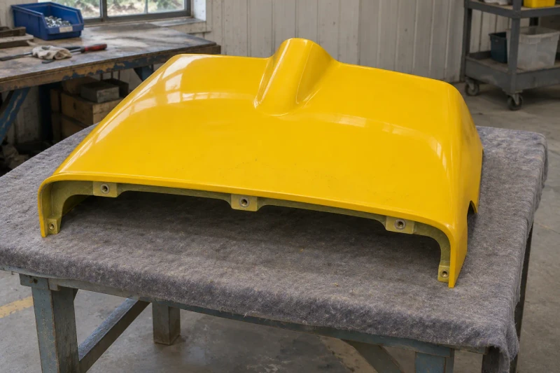
How we customize the parts.
Clearance under the raised crown
The crown and broad face are shaped from your equipment drawing, keeping the clearance it shows above the parts beneath. Side returns are trimmed back where moving components pass close by.
Fixing points matched to the machine
Holes or insert provisions sit at your specified mounting positions, with local reinforcement behind them. They are placed where a technician can reach the fasteners.
Edges trimmed for service removal
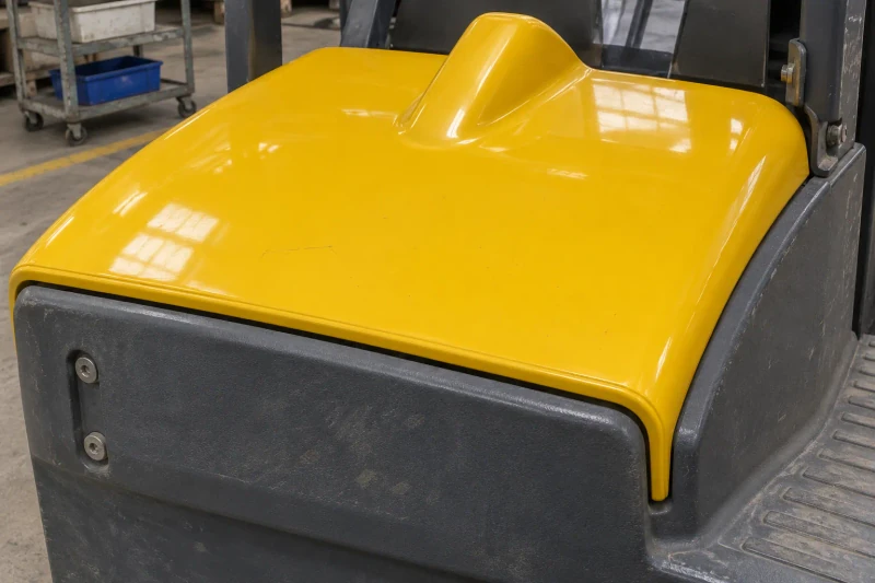
The perimeter is trimmed to the surrounding bodywork and to the direction the cover lifts away during service. Gelcoat color and surface finish are agreed for the large visible face.
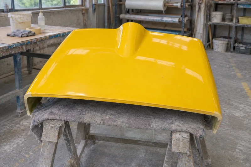
Mold the profile and prepare the edges
We mold the cover with a gelcoat face and the specified fixing provisions, then trim the perimeter and prepare the mounting points. The first cover is checked on your machine or an agreed fixture for edge clearance and removal. Production covers follow the accepted part and are packed to protect the face and edges.
Prepared mounting areas. Planned removal clearance.
The cover carries its clearance envelope, trim perimeter and fixing references together. The machine team can review the first part against the equipment and its service-removal direction before repeating the shell.
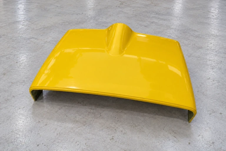
Clearance carried into the cover
The raised profile follows the equipment beneath it.
Prepared mounting positions
Reinforced fixing areas follow the machine interfaces.
Removal considered with the trim
Perimeter edges follow the planned service-lifting direction.
Dimensions and design options
- Reference part size
- 820 × 580 × 150 mm
Forklift cover shape and service access
The curved face, raised crown and side returns are shaped together around the machine. Crown clearance, edge depth and any part split depend on the mounting points and the route needed to remove the cover for service.
One-piece cover with a raised center
A narrow rounded crown at the rear blends into the broad curved face, giving room for equipment underneath. The bowed front edge and side returns meet the surrounding bodywork.
Deeper returned sides
Longer side returns carry the cover down to the bodywork line and hide more of the machine. Reliefs in the lower edge keep the deeper sides clear of nearby parts when the cover is lifted off.
Separately removable front section
A cross joint separates the broad front face from the raised rear section when a one-piece cover cannot be removed along the service route. The split also changes the support and fixing details at the joint.
Mounting lands on the underside
Reinforced lands on the underside carry the fixing holes or insert provisions at your attachment points. Their positions are set so a tool can reach each fixing past the side returns.
Key dimensions for the cover
W and D describe the overall footprint, while H measures the crown above the mounting datum. The inner surface must also leave clearance around the equipment beneath the shell.
- W · overall width
- Overall width, changes in width and corner radii follow the surrounding bodywork.
- D · front-to-back depth
- Overall depth includes the front-edge curve and rear boundary. The crown and any split are positioned from the same datum.
- H · crown height above the mounting datum
- Outer crown height is measured from the mounting plane. The equipment envelope also defines the usable clearance beneath the shell.
- Side returns and mounting details
- The side returns include edge reliefs where needed for nearby parts. Hole or insert positions must also leave room for tools to release the fasteners.
Clearance, fixing access and cover removal
The first cover is checked on the machine or an agreed fixture before production. The section shows the shell over a dashed equipment envelope, with the clearance gap and lift-off direction marked.
- A · clearance around the equipment
- The inner crown, broad face and side returns are checked against the equipment, including the clearance needed around its moving parts.
- B · mounting and edge contact
- Fixing points, reinforcement and mating surfaces are located from your drawing, including where the cover bears and where it needs a gap. Fasteners are supplied only when listed in the quote.
- C · removal route
- Lift-off clearance after the fixings are released determines whether a one-piece cover can be removed. Edge trim or a split front section can be reviewed before tooling where clearance is limited.
Surface appearance, construction and first-fit checks
- Gelcoat color and surface
- Gelcoat color and surface finish cover the broad face and crown. An existing-bodywork reference supports finish matching where the cover sits beside other panels.
- Construction and prepared edges
- Laminate construction and local reinforcement depend on how the machine is used and how the cover is mounted. The perimeter is trimmed to the adjoining bodywork and specified clearances.
- First-fit checks and packing
- The accepted sample is checked for edge fit, fastener access and removal on the machine or fixture. Finished covers are supported in packing to protect the face and side returns.