Floor panels divided around the equipment.
From one platform layout to a set of fitted tread panels. We develop the panel divisions, mold the floor sections and prepare openings for pipes and maintenance access.
Cutouts, support ribs and lift-out sections are prepared for the platform layout rather than trimmed at random on site.
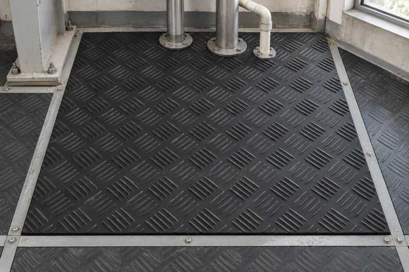
- Face
- Molded tread face
- Construction
- Reinforced underside
- Panel sizing
- Cut to your panel schedule
Keep service points reachable through the floor.
The platform has equipment bases and pipes passing through the floor. A single large panel would cover service points, so the floor is divided around the support frame and the areas that need to lift out.
Equipment interrupting the floor
Pipework and machinery bases need openings in specific panels rather than across the whole platform.
Panel loads meeting the frame
Edges and underside ribs must follow the actual support spans and load requirements.
Service points below the surface
Selected pieces need to lift out while retaining the tread direction of the surrounding floor.
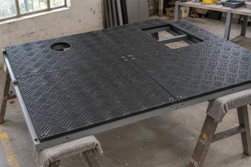
How we customize the parts.
Cutouts around the machinery
Pipe openings and equipment recesses are cut only in the panels that need them, leaving the other sections full-size.
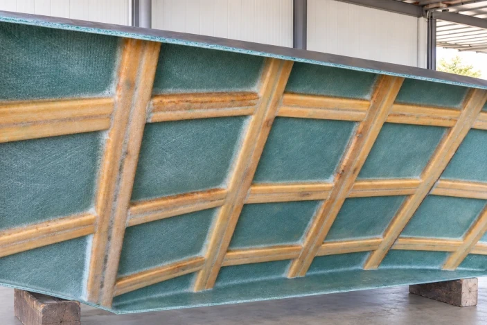
Ribs above the supports
Underside ribs and panel edges line up with the frame contacts, and panel thickness is set for the specified spans and loads.
Separate access pieces
Service points get their own lift-out pieces, with the tread running in the same direction as the surrounding floor.
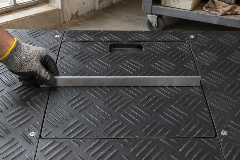
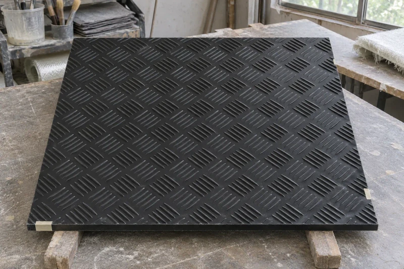
Mold and trim
We form the tread faces and ribs, then trim each outline, cutout and fixing hole to its part drawing. We check panel sizes and openings, then mark each piece with its place in the floor plan so the set can be laid out quickly on site.
A panel schedule the assembly team can follow.
The panel schedule places openings and lift-out sections where the equipment layout needs them. The installation team can work from prepared sections while keeping the planned service points accessible.
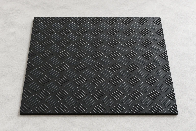
Openings placed by the schedule
Equipment cutouts are prepared in the sections that need them.
Support contacts coordinated
Ribs and edges follow the platform frame and specified spans.
Service pieces remain separate
Lift-out panels retain access through the surrounding floor.
Dimensions and design options
- Material
- Solid FRP panel
- Reference surface
- Molded diamond tread
- Panel dimensions
- Defined by layout
- Acceptance
- Load and slip criteria specified per project
Choose your floor-panel layout
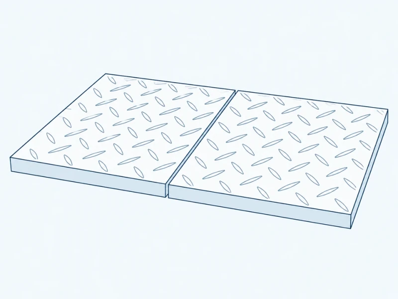
Repeated floor modules
Solid panels form repeated floor sections, with edges and joint gaps matched to your supports.
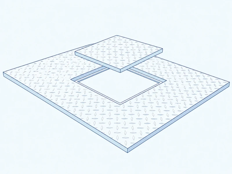
Access panel arrangement
Removable floor sections expose maintenance areas, with edges shaped for the specified supports and retention arrangement.
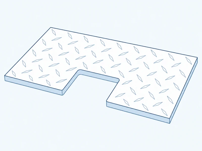
Cutouts around obstructions
Shaped cutouts fit around equipment and pipes, with finished edges at the specified supports.
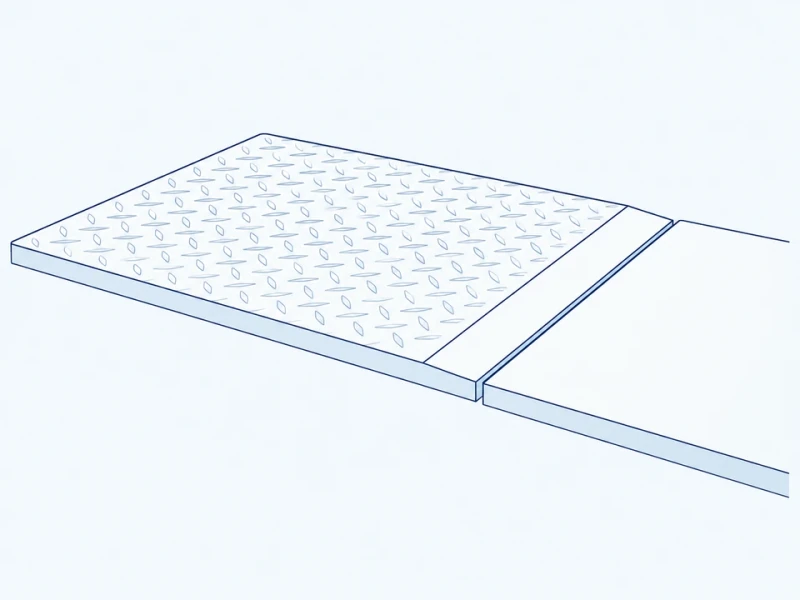
Threshold or edge transition
Shaped edges meet adjoining floors, with the level change and supporting detail shown on your section.
Floor panel size and joining edges
Panel layout over the supports
Diamond-tread panel sizes can follow your floor layout and the specified distance between supports.
Separate floor-panel edges
Joint edges and removable panel boundaries are shaped to separate the fixed floor from the maintenance sections.