Bicycle parking shaped around the room.
Custom fiberglass wheel channels for circular parking pods or wall rows, with retaining fittings and assembly work matched to your order.
Molded sections bring wheel spacing, retaining fittings and the available floor plan together. Images are concept visualizations of possible layouts and fabrication details.
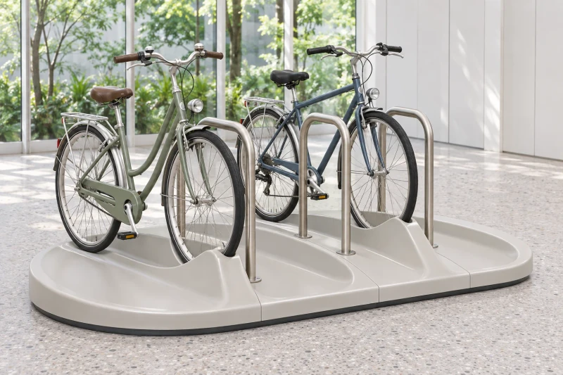
- Process
- Hand-laid wheel channels
- Layouts
- Circular pods or wall rows
- Hardware
- Hardware by agreement
Make the parking layout work for riders.
A bicycle room may need parking around a column or along a wall. The channel shape, bicycle spacing and approach space need to work together so riders can put their bicycles in and take them out.
Different wheels, one channel profile
The channels need room for the specified tires while keeping the wheel aligned with the retaining fittings.
Space to park and remove a bicycle
Closely packed positions still need a usable approach. The room layout has to account for the bicycle as it is moved into place.
Molded sections meeting metal fittings
Retaining rods, loops and floor contacts need accessible attachment areas in the fiberglass sections.
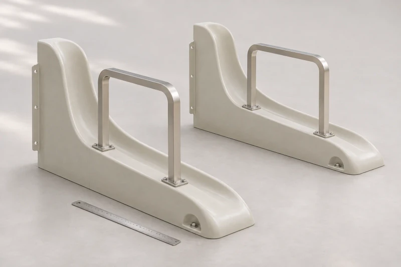
How we customize the parts.
Wheel channels for your bicycle range
Channel width and curve follow the wheel sizes and tire widths you specify. The shape also leaves space for the chosen retaining fittings.
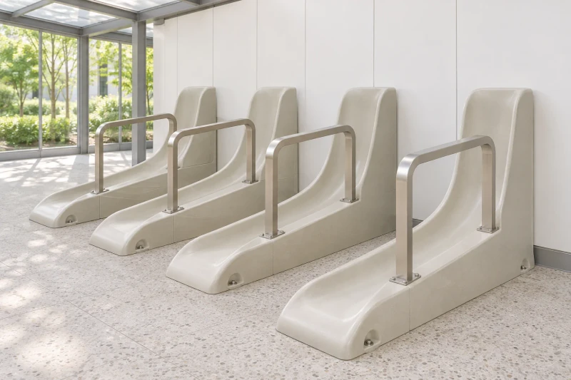
Circular pods or straight rows
Separate molded sections can form a circular pod or a wall row. Position spacing is planned around the room riders need to park and remove their bicycles.
Attachment areas for selected fittings
Reinforced fixing areas follow the rods, loops and supports in the order. Floor or wall contacts are developed around your site details.
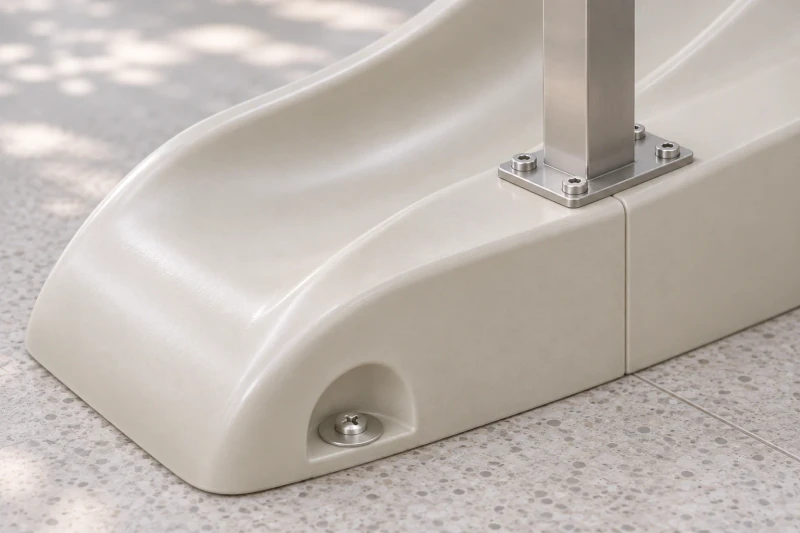
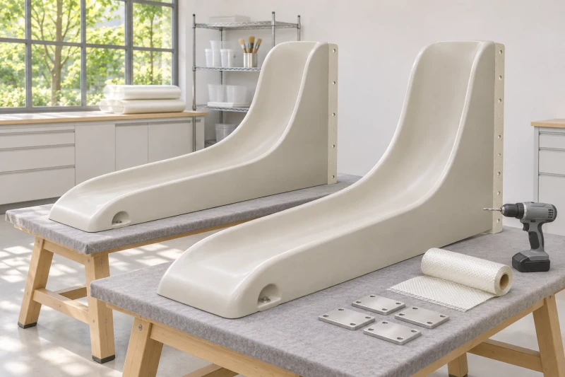
Mold and prepare the channels
The channels are formed by hand lay-up, with the agreed attachment areas. Edges and fixing positions are prepared for the selected assembly. We check channel openings and fitting positions against the drawings, then protect the curved edges and prepare the order for delivery.
A clear place for every bicycle.
The parking plan and molded channels share the same wheel spacing and attachment references. Installers can position the sections and selected fittings as one coordinated arrangement.
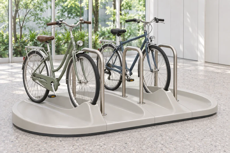
Layout carried into the parts
Wheel spacing and room access follow the same parking arrangement.
Defined fixing areas
Retaining fittings meet the prepared contacts in the molded sections.
Sections considered for replacement
Accessible connections allow replacement sections to be planned with the original layout.
Dimensions and design options
- Assembly
- Molded FRP sections; metal retaining hardware optional
- Layout
- Circular or wall-side arrangement by design
- Fixing
- Hardware and floor or wall fixing by approved drawing
Bicycle-parking arrangements
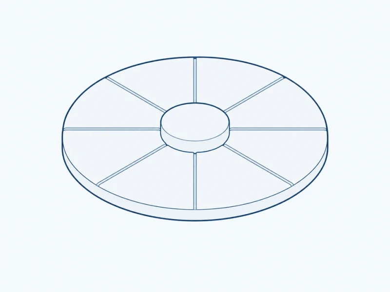
Circular pod
Wheel-support positions sit around a central molded body.
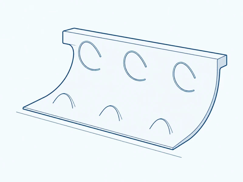
Wall-side row
Repeated support sections form a parking row beside a wall.
Paired parking island
Two back-to-back support rows form one parking island.
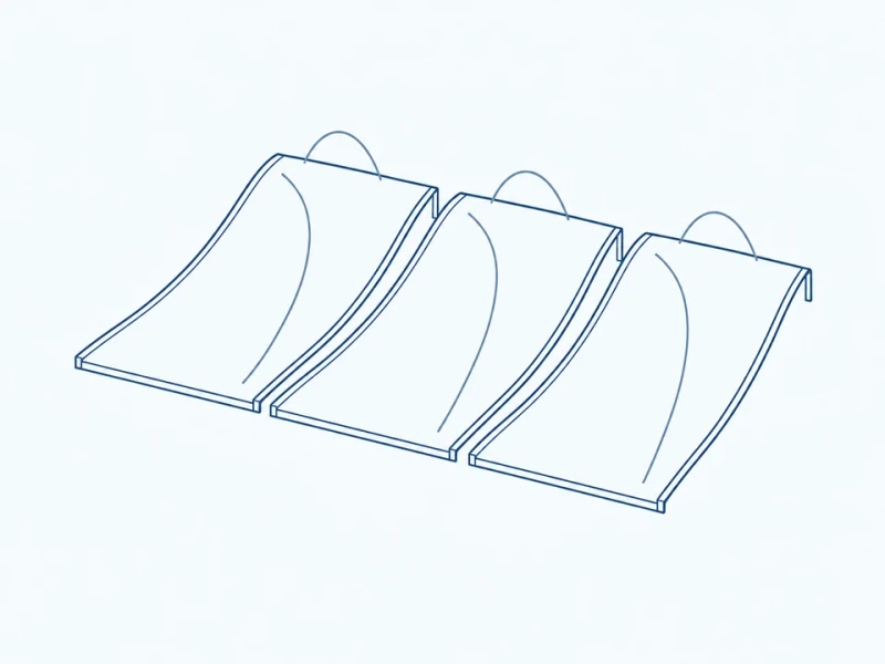
Sectional pod layout
Separate molded sections join together to form a longer parking arrangement.
Bicycle positions and support shapes
Parking spacing and retaining height
The plan locates the parking-position centers. In the side elevation, retaining height runs from the base underside to the upper retaining-loop centerline, and base depth covers the full molded foot.
Wheel-support profile and fixing base
The molded wheel-support profile and base contacts are shaped to your bicycle layout and floor or wall fixing.