Wood-grain covers that leave the mechanism accessible.
Custom fiberglass housings give engineered waterwheel supports a coordinated decorative finish, with panel divisions and access planned around the mechanism.
Shaped exterior panels conceal the supports while retaining separate inspection access.

- Component
- Decorative support housings
- Surface appearance
- Wood-grain, color to approved sample
- Mechanism
- Mechanism supplied separately
Follow the landscape design around moving equipment.
A landscape waterwheel brings together a large moving wheel, structural supports and equipment that needs inspection. Decorative housings must follow the intended appearance without taking over the job of the structure or obstructing the mechanism.
A decorative face around structural supports
The covers need to follow the landscape elevation while leaving the mechanism’s specified movement clear.
Inspection at the bearing and connections
Selected faces must come off without disturbing the rest of the decorative exterior.
Wood grain across adjoining pieces
Grain direction, panel divisions and handling sizes have to work across the complete set.
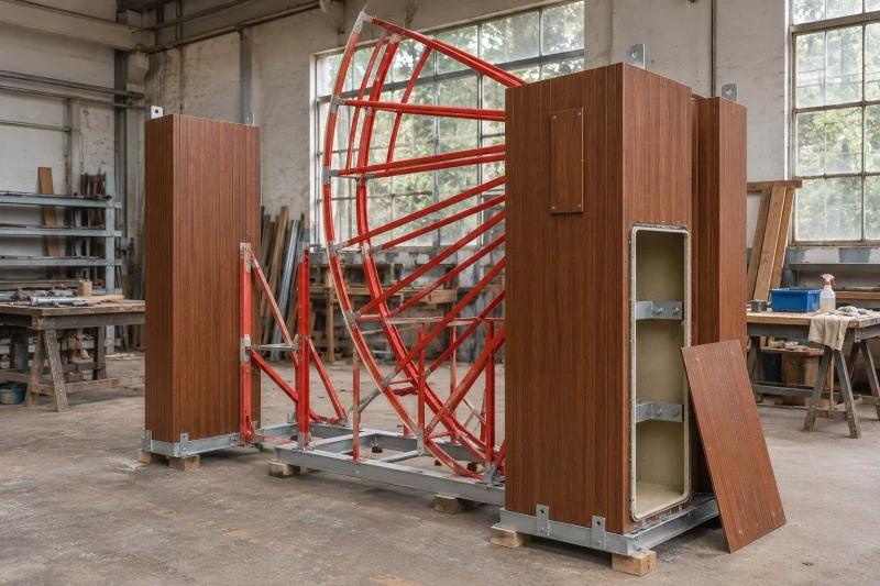
How we customize the parts.
Shaped around the supports
Cover outlines follow the approved landscape elevation and the support dimensions. Clearances around moving parts follow the figures from your wheel and mechanism designer.

Removable faces for inspection
Panel joints and fixings sit at the bearing and structural-connection access points. Each maintenance panel comes off on its own, without disturbing the rest of the set.
Wood-grain direction across the set
Grain direction, color and joint appearance follow an approved sample, so adjoining pieces line up visually. Piece sizes also respect the lifting space and transport limits at the site.
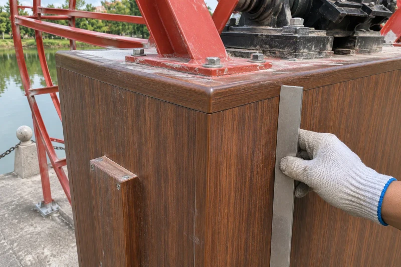
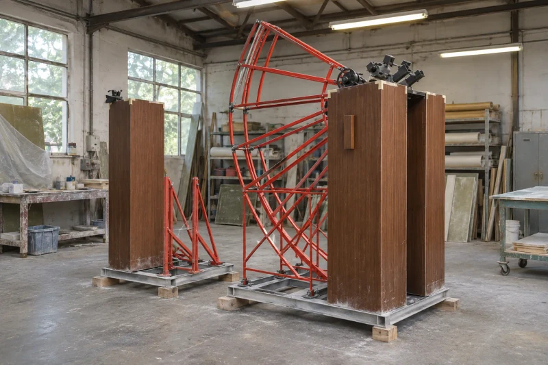
Approve the surface appearance, then make the sections
A wood-grain sample is approved for texture and color first. The fiberglass sections are then made around the structural envelope. Each piece is checked against the agreed layout and marked by location. Packing protects the finished faces for the planned delivery.
A coordinated exterior with removable access panels.
The cover set follows one grain and joint reference while retaining separate maintenance panels. Inspection access is part of the exterior arrangement, so it does not depend on dismantling the whole decorative set.

A continuous decorative appearance
Grain direction and panel joints share one finish reference.
Separate inspection panels
Selected covers can be removed around the mechanical connections.
Sections sized for the site
Panel divisions consider transport and lifting access.
Dimensions and design options
Support housings and maintenance access
Vertical wood-grain faces hide the support structure while leaving the mechanical access your designer needs. Open sides, removable faces and transport splits are planned from the support and maintenance drawings.
Open-backed upright housing
Full-height faces and corner returns follow the support outline. The open back allows installation or service access, and the top edge is kept clear of the mechanical connections.
Separate wraparound sections
Two L-shaped sections fit around a support that is already standing, where a one-piece housing cannot be lowered over it. Joint edges, return widths and fixing access are set from the installation sequence.
Removable inspection panel
A smaller panel opens access to a bearing or structural connection without removing the whole housing. The grain continues across the panel so it follows the surrounding face.
Housing divided for transport
Upper and lower sections reduce the height of each piece for handling and follow the site installation order. The split line is set from the largest piece that can be transported, with the grain aligned across the joint.
Housing dimensions
The support drawing and landscape elevation set the cover envelope. Width, depth and height are coordinated with the top connection, base clearance and the space needed to remove each section.
- W / D · cover envelope
- W and D describe the outer cover envelope. The support and mechanism need their own clear space inside it, which is separate from the decorative outer shape.
- H · height and top termination
- The site datum sets the bottom and top of each housing, with the bearing or shaft connection levels and any base offset recorded from the same reference.
- Section divisions and handling size
- The access route, transport limits and available lifting space determine where large covers are divided.
- Openings and removable faces
- Inspection openings, top reliefs and removable panels follow the mechanism drawing, with room to reach the fixings and withdraw each face.
Access behind the decorative covers
A removable face should open the maintenance area without disturbing the supporting structure. The plan section shows a housing around a dashed equipment envelope, with the front face pulled away to show the access direction.
- A · support and mechanism clearance
- The housing is checked against the supports, bearing access and wheel movement. Clearance and inspection requirements come from the mechanism designer.
- B · independent panel removal
- A panel can be removed independently only if its fixings can be reached and there is enough space to lift and handle it. Removal direction and panel weight therefore affect the access layout.
- C · cover fixing regions
- Edge returns, local reinforcement and fixing points follow the structure drawing. The covers are decorative skins; the wheel, bearings, drive, structure and foundations are supplied separately.
Wood grain and site exposure
- Grain direction and joint appearance
- Grain scale, direction, color and joint alignment are approved on a sample. Each face is marked so adjoining pieces follow the landscape elevation.
- Waterside exposure and cleaning
- Splash, sunlight and cleaning conditions influence the surface finish and any site-specific exposure checks.
- Site sequence and protected delivery
- Panels are marked by support location and installation order. Packing protects the broad faces and edges, and removable pieces stay identifiable for later maintenance.