Custom FRP Bone Densitometer Housings
We mold the scan-head shrouds, column covers, long table skirts and end caps around your densitometer frame and motion model. Your drawings set the cover splits, clearances and fixings; a first fitted set confirms the joining edges and service access. Components in the imaging path require your specified construction and acceptance checks.
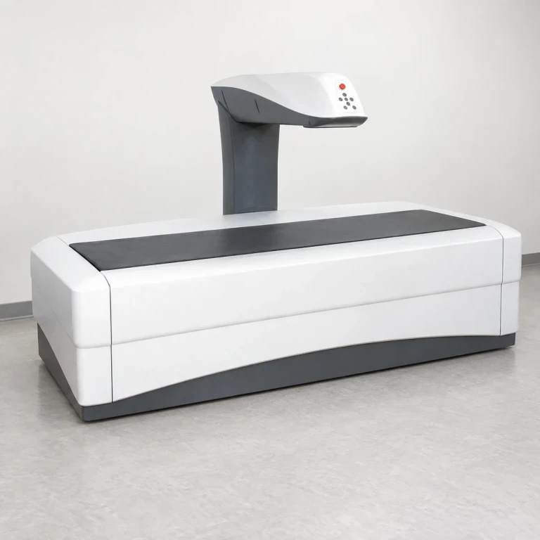
Densitometer assembly reference locating the scan-head shroud, table skirt and end caps. We supply the specified exterior covers; the scanning system, patient support and moving structure are separate.
Image credit: ·
Densitometer cover parts
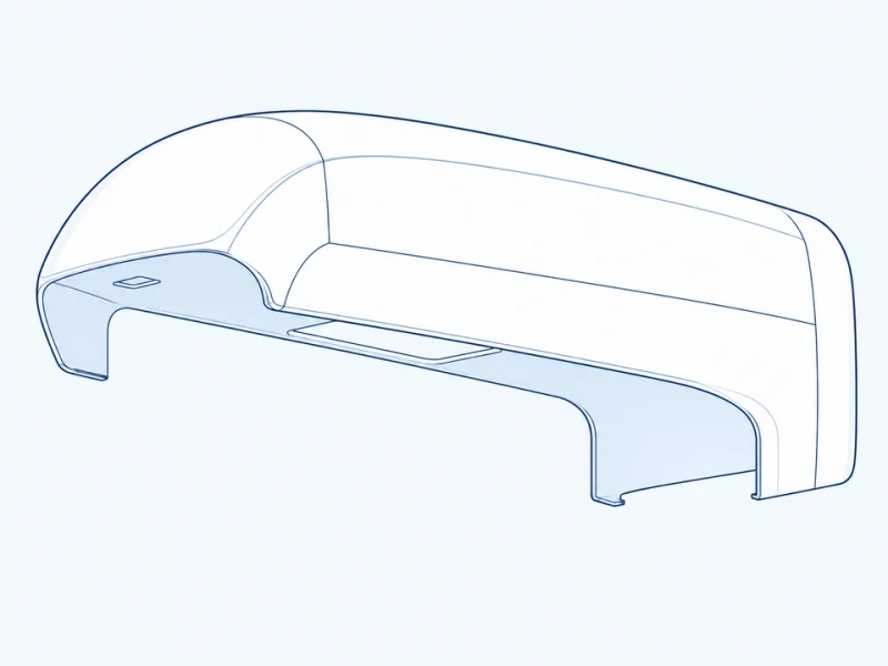
Cantilever head cover
A cantilever upper shroud follows the scan head, with custom underside edges and control openings.
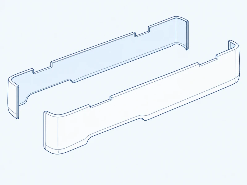
Long table skirt
A long curved skirt follows the table side with a separate removable service edge.
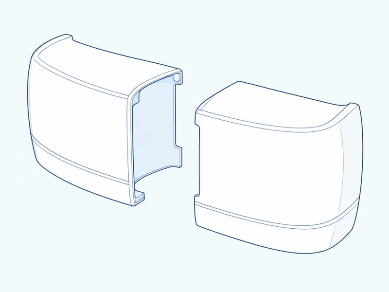
Rounded table end cap
A rounded end cap closes the table side with a molded return meeting the chassis.
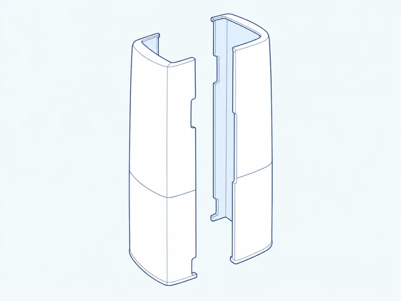
Column cover pair
Paired upright shells surround the scanning column with separate sections for rear service access.
Customize the densitometer covers
Head and table profiles
Custom molds follow your cantilever-head outline, column sections and table-side curvature.
Attachments and openings
Mounting areas connect each cover to the frame, while control cutouts and removable edges leave access to the equipment behind it.
Matched cover surfaces
Joining returns, rounded edges and exterior color are coordinated across the head, skirts and end caps.
Densitometer cover references
Table and scan-head size
Table length and width locate the surrounding skirts and end caps. Head-to-base height describes the overall space occupied by the column and scan-head covers.
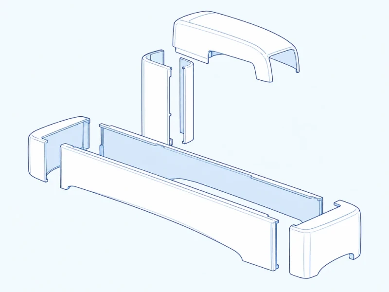
Separate head, column and skirts
The head shroud and split column shells cover separate assemblies. Long table skirts meet the rounded end caps along returned edges.