A dashboard that makes room for the cabin equipment.
Molded fiberglass dashboards with tray recesses, instrument openings and control clearances developed around the cabin equipment you select.
Instrument apertures, molded recesses and control clearances are settled before repeat parts are made.
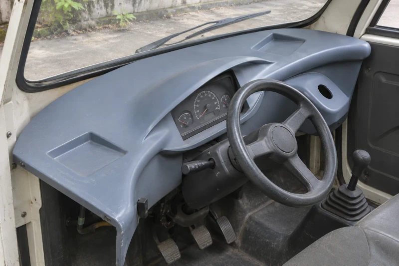
- Component
- Molded dashboard face
- Openings
- Instrument and control openings
- Review stage
- First-fit review
Bring the controls together in a compact space.
In a compact vehicle, the instruments, steering column and shift lever share a small space. A dashboard needs to follow the cabin width while leaving room for these parts, their movement and the connections behind the face.
Instruments with depth behind the face
Visible apertures also need space for connectors, brackets and fastening access.
Steering and shift-lever movement
The lower dashboard has to clear the controls through the movement defined by the cabin design.
One face inside a limited cabin width
Tray recesses, visible contours and mounting areas all compete for the same compact space.
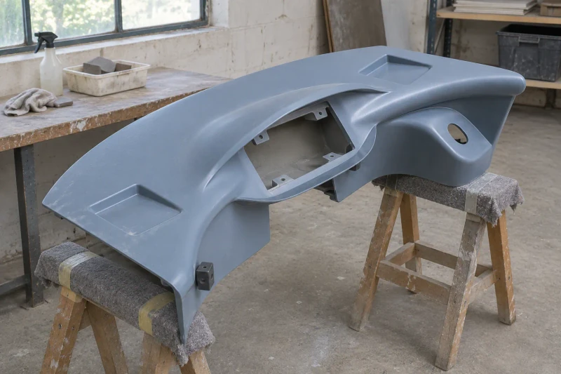
How we customize the parts.
Instrument openings and space behind them
The face openings follow your gauges or instrument module. Depth behind the panel allows for the specified connectors, fasteners and mounting brackets.
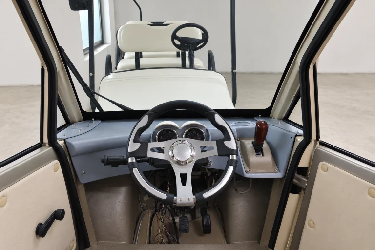
Clearance for steering and shifting
The lower contours and side opening follow the steering-column and shift-lever positions. Their movement is reviewed against the cabin arrangement before the trim is finalized.
A molded face with useful recesses
Tray recesses and dashboard contours can be formed together. Your team reviews instrument visibility, control reach and the visible color and gloss during development.
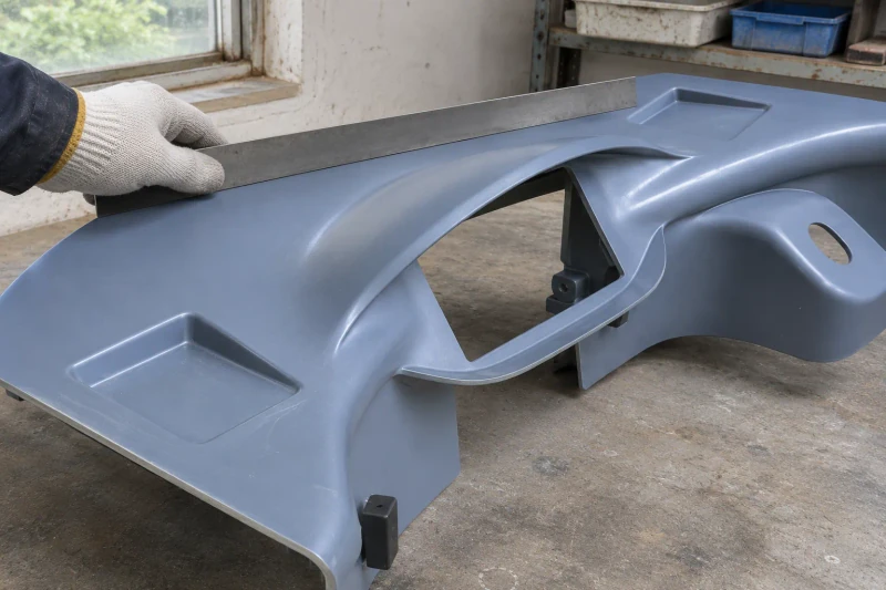
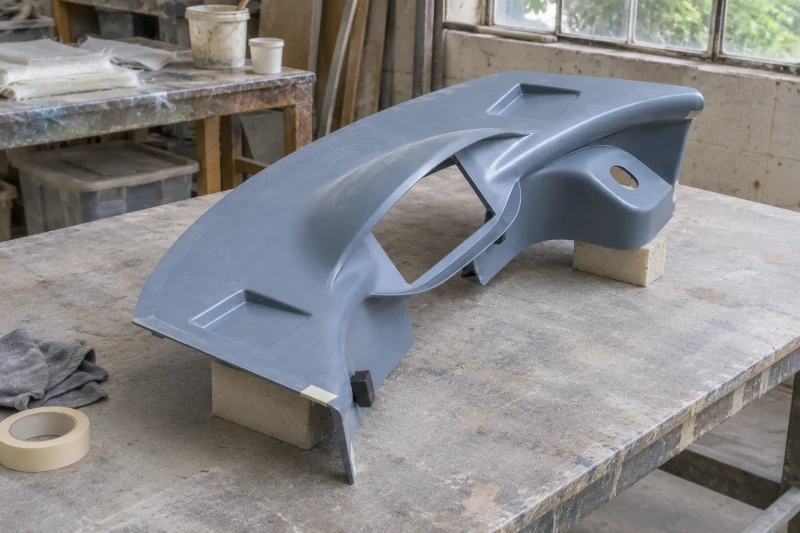
Make the molded dashboard
We form the curved face and recesses, trim the instrument and control openings, and prepare the mounting areas to the agreed cabin drawing. Your team checks the first part in the cabin with its equipment. We incorporate the agreed fit changes before making and packing the repeat parts.
Fit decisions before repeat supply.
The first dashboard brings instruments, controls and trim edges into one cabin review. Agreed changes can then guide repeat parts, reducing separate fit decisions during vehicle assembly.
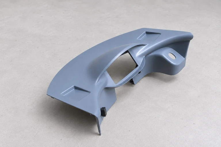
Fit decisions on the first part
Instruments and controls can be reviewed together in the cabin.
Prepared equipment openings
Apertures follow the selected modules and their rear connections.
One repeat-part reference
Agreed trim, mounting and finish details guide subsequent dashboards.
Dimensions and design options
- Part
- Dashboard fascia and instrument pod
- Material
- Fiberglass (FRP)
- Lead time
- Confirmed after design review
- Surface appearance
- Painted in your cabin color, texture and sheen
Choose your dashboard layout
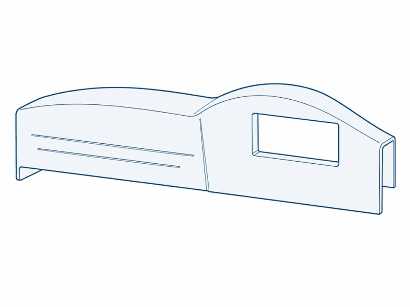
Full-width fascia shell
One full-width molded face joins the passenger side and raised driver instrument pod across the cabin.
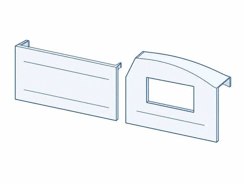
Separate instrument pod
A separate removable instrument surround allows access to devices without taking out the full passenger fascia.
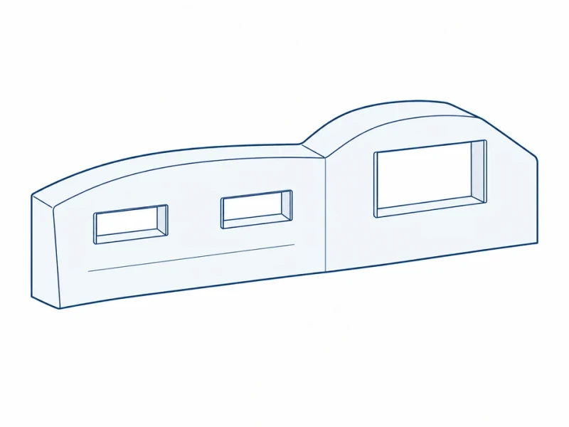
Vent openings
Vent openings and rear duct-contact shapes fit the selected outlets in your cabin ventilation layout.
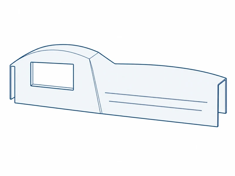
Handed cabin layout
Left- and right-hand driver versions place the instrument pod, control openings and mounts around the steering layout.
Fascia width and raised instrument area
Cabin span and pod depth
The front view measures fascia width and instrument-opening width. The side profile measures the pod’s outside front-to-back extent; space for devices, connectors and brackets behind the face is checked separately.
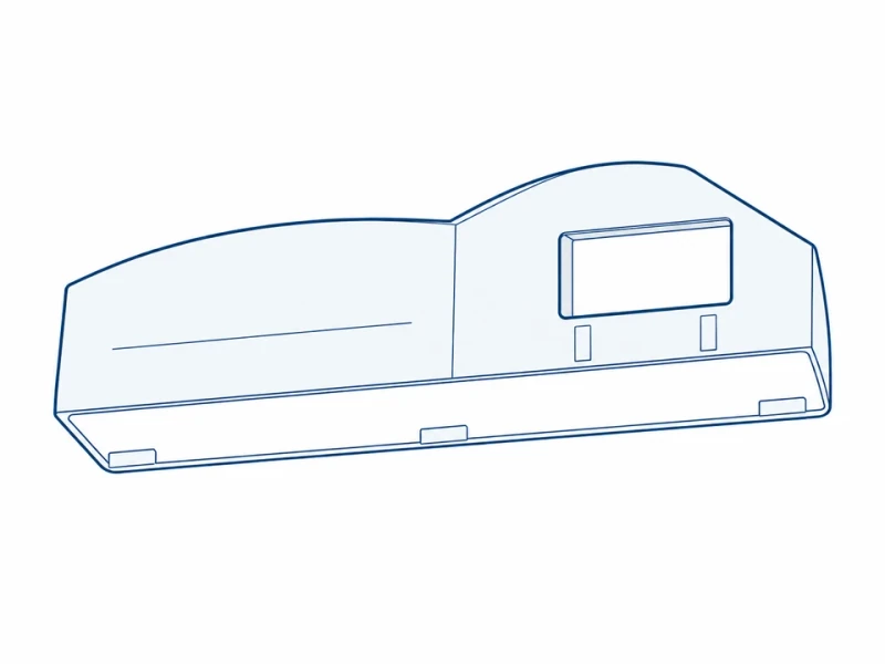
Screen opening and lower mounting edge
A raised instrument face can include screen and control apertures, with a returned lower edge and specified mounting areas.