Fiberglass Rooftop Equipment Screens
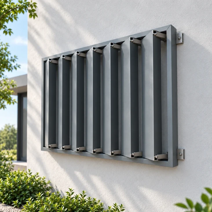
Fiberglass screens hide rooftop equipment behind louvered, solid or patterned bays. We make the panels to your screen heights and post layout, with matching corners and removable sections along the service route.
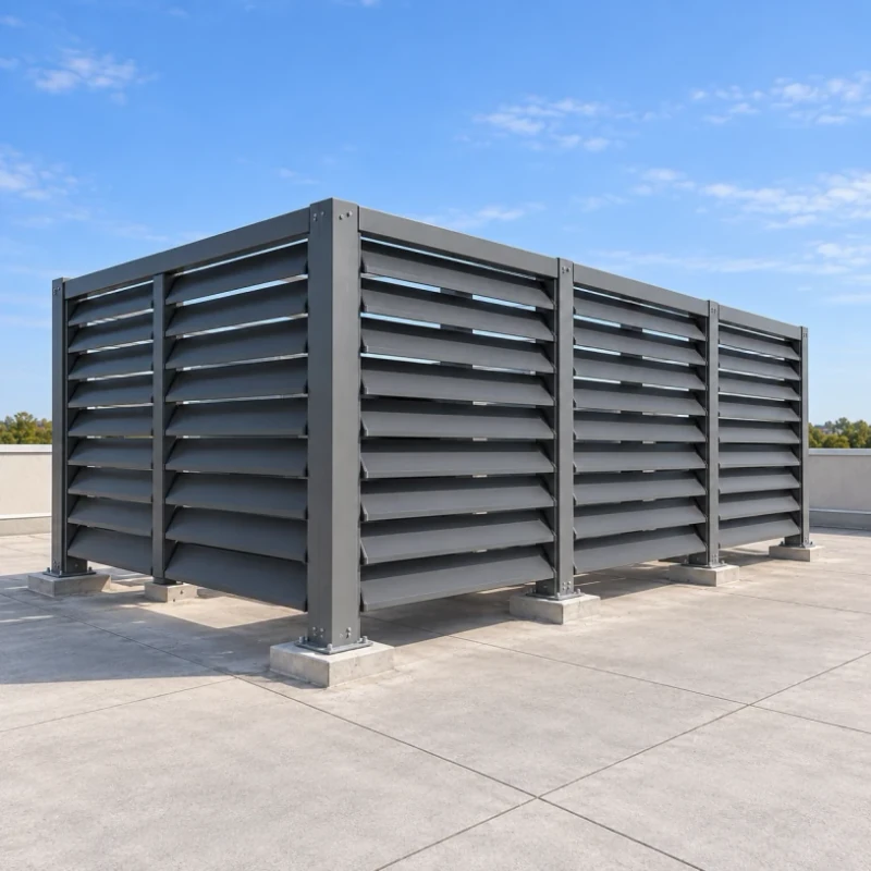
Fiberglass louvered panels forming a modest rooftop equipment screen.
Image credit: Fiberline Building Profiles ·
Choose your rooftop screen face
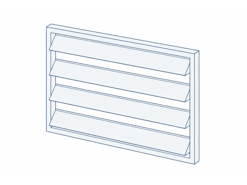
Louvered screen bay
Angled blades block direct views of the equipment, with blade gap and depth set to your layout.
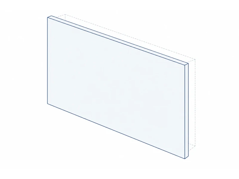
Solid architectural panel
A solid fiberglass face conceals the equipment and forms a continuous band around the roof area. Wind loads and roof attachment are designed for each project.
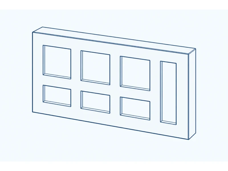
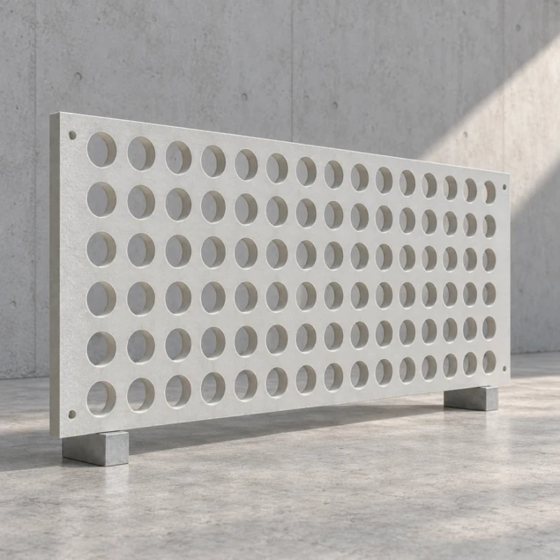
Patterned open module
Patterned openings echo the facade, with solid fixing zones around them. The open area follows the equipment maker's ventilation requirements and the roof layout.
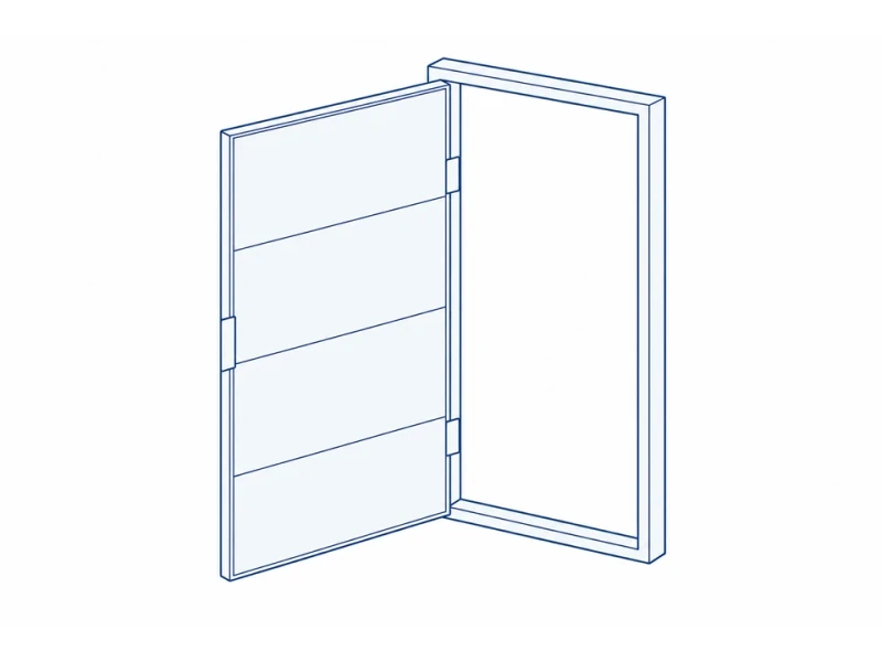
Service gate or removable bay
A gate or lift-out bay provides an opening for maintenance and equipment replacement.
Customize the rooftop screen
Bays and corners
Panel or blade sections are made to your screen heights, with matching corners and ends that fit between the support posts.
Service sections
Removable panels and gate-shaped sections have fixing areas prepared for the hardware shown on your drawings, so technicians can reach the equipment.
Surface appearance seen from the street and roof
Color and texture can cover fronts, backs, blade ends and opening edges wherever the screen is visible from the street or neighboring buildings.
Screen size and support-post layout
Bay height and service space
The elevation shows the screen bay’s width and height. The plan measures service clearance from the screen to the equipment or maintenance envelope.
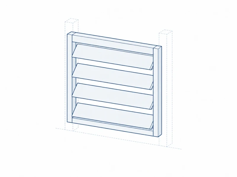
Louver bay between separate posts
Framed louver bays fit between separate support posts. Blade angle and spacing follow the sightline design and the equipment maker’s ventilation requirements.