Wind Turbine Components
Turn a turbine concept into physical blade components your team can assemble and evaluate. We mold custom curved FRP shells with joining and attachment options for development builds and repeat parts; this example follows a vertical-axis rotor.
Where it is used
Curved blade shells for a rotor development build
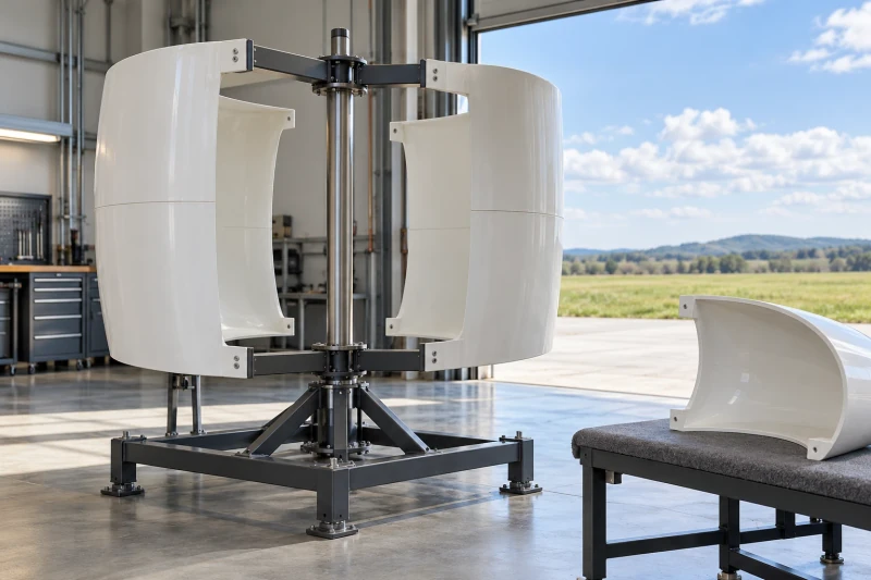
In a vertical-axis rotor development build, curved fiberglass shells attach to metal arms around a central shaft. The blade profile and mounting areas have to fit the same assembly model. A sample build lets the turbine team check those interfaces before ordering repeat parts.
- The molded surface follows the full blade model and its section references.
- Attachment tabs and insert positions must match the metal arm drawings.
- Tooling, joining and inspection all work from the same component revision.
Our approach
Build each part to the turbine design
Check the blade attachment against the rotor hardware
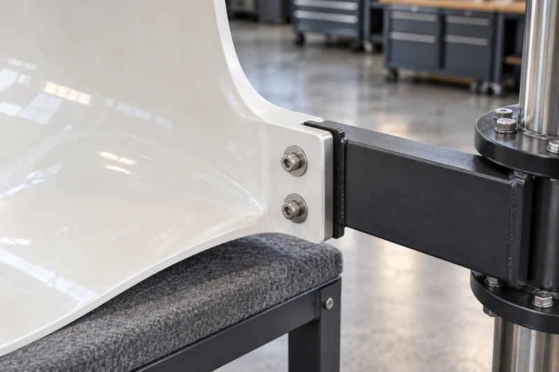
We compare the blade shape and attachment tabs with the rotor-arm drawing. A sample fit checks mating faces, hole positions and access to the fasteners, using the insert and joint details specified by the turbine designer.
The sample checks the blade-to-arm connection before the same detail is repeated.
Carry the curved profile through tooling and sampling
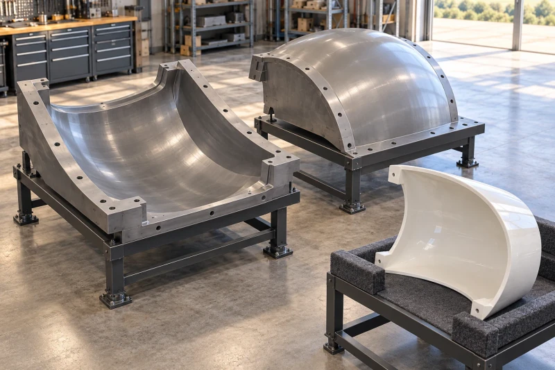
For an RTM component, we build the closed mold from the full blade model and cross-section drawings. Resin is injected into the glass reinforcement inside the mold. The first shell is checked against the specified profile, trimmed edges and attachment details.
Tool and sample are both checked against the full profile, including the attachment areas.
Supply the shells for the next assembly stage
We can supply open shells or include specified bonding, insert fitting and seam finishing. The component specification identifies the laminate, drawing version and required checks for dimensions, finish and weight.
Your team receives shells and records matched to its next assembly stage.
What we can supply
Supplied components
Shells with specified attachment preparations
The blade shells follow the approved profile, with the specified edges, attachment tabs and insert locations. Bonding and seam finishing are included when they form part of the component order.
Samples for the next design decision
Open shell segments, joined sections or attachment-ready ends can support different development reviews. Each supplied component is tied to the blade revision and the agreed checks so your team can relate the result to the design being evaluated.
Delivery and rotor responsibilities
Packing supports protect curved edges and tabs. Rotor hardware, assembly, structural validation and complete-turbine acceptance stay with your turbine program.
Blades, housings and cable conduits
An RTM blade-shell manufacturing example
- Blade shells with the seams and attachment points built in.
The RTM tooling, laminate and joined edges follow the same released component design.