Blade shells with the seams and attachment points built in.
Bring your blade model into molded fiberglass shell sections. Our component service covers RTM molding, specified bonded joints and attachment preparations, with construction and checks agreed with your turbine design team.
The RTM tooling, laminate and joined edges follow the same released component design.
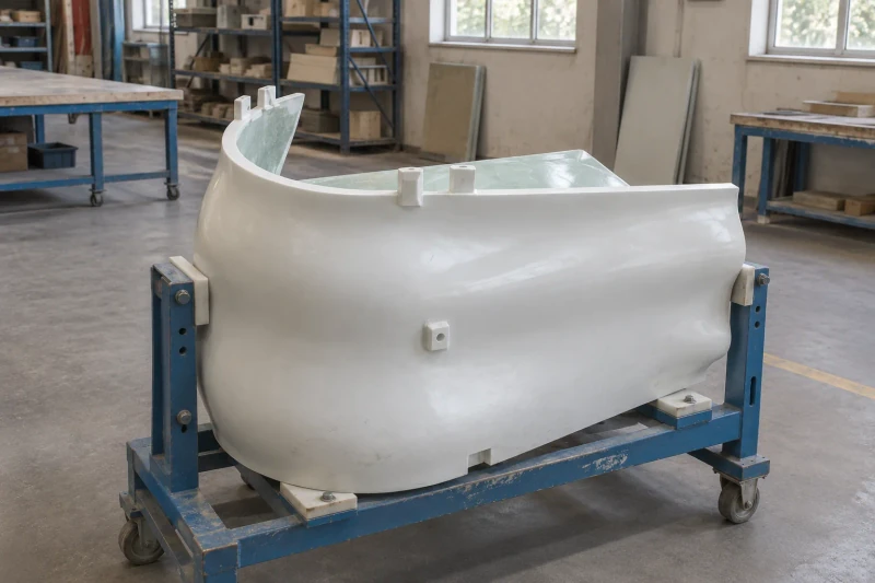
- We make
- RTM shell molding
- We coordinate
- Bonded section joints
- You receive
- Agreed attachment tabs
Carry a changing blade section into repeatable shells.
A curved blade shell needs more than the right outer outline. Cross-sections, joined edges and attachment positions must follow the same component design. Bringing those details together before tooling helps establish which shell sections will be molded, joined and supplied for the turbine team's assembly.
Changing sections along the blade shape
The mold needs to carry the approved curves and cross-sections into the supplied shells.
A laminate suited to the component duty
Fiberglass layers and resin must follow the released construction requirements.
Joined edges and attachment positions
Seams, tabs and specified inserts have to meet the same component assembly drawing.
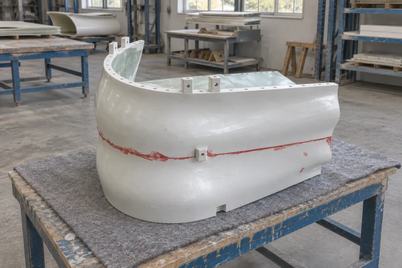
How we customize the parts.
Curve and cross-sections
The RTM tool is built from your approved blade model. Each molded shell then follows the same changing section shape and the same mating positions with the rest of the rotor.
Fiberglass construction
We mold to the fiberglass layers and resin in your laminate specification. If the laminate has not been selected, we review its construction and the component inspection plan with your design team against the design loads.
Seams and attachment tabs
Shell sections are bonded, trimmed and fitted with tabs or specified inserts where shown on the component drawing. Seam finishing follows the scope listed for the supplied shells.
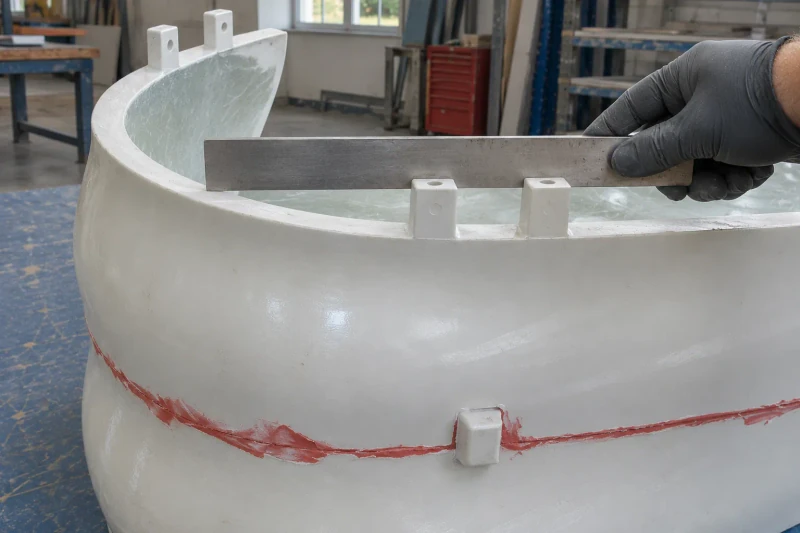
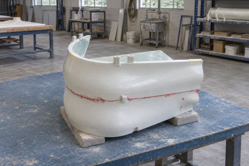
Mold and join the sections
Shell sections are RTM molded to the agreed laminate. Specified joints are then bonded, edges trimmed and seams finished as ordered. Each part is checked against the agreed criteria. Curved shells are packed on padded supports that carry the broad surfaces and keep attachment tabs clear of the crate.
One component plan from tooling to joining.
The shell sections carry common cross-section, seam and attachment references into the component assembly. Molding and joining follow the same defined construction plan rather than separate interpretations of the blade shape.
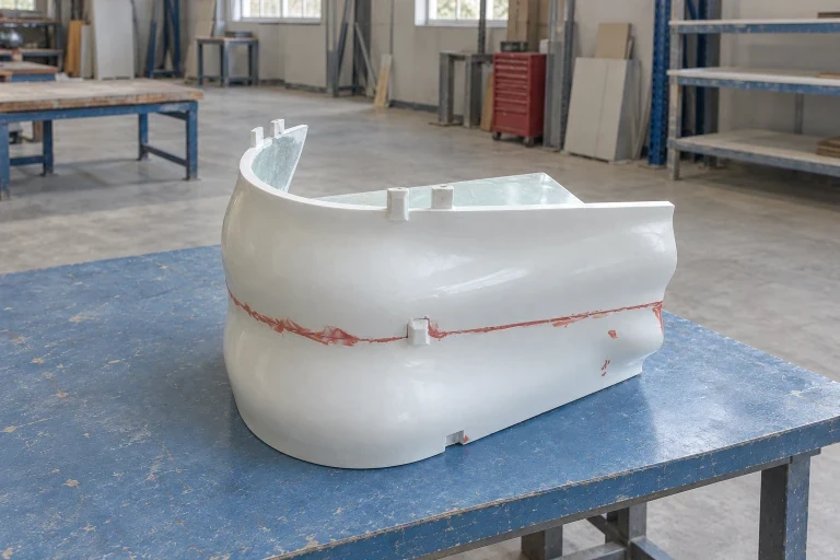
One shape carried into the tool
The mold follows the released curves and cross-sections.
Joining details developed with the shells
Seams and attachment positions follow the component drawing.
A shared construction reference
Molding, laminate and finishing requirements guide the same component order.
Dimensions and design options
- Supplied as
- Open shells, closed sections or attachment ends
- Production basis
- Approved drawing or sample
- Reference geometry
- Curved vertical-axis blade component
- Reference molding method
- RTM
- Design basis
- Geometry, laminate and attachments from the turbine designer
Wind-blade component options
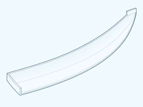
Curved shell segment
An open curved shell has trimmed edges and attachment lands so your assembly team can join or close the section.
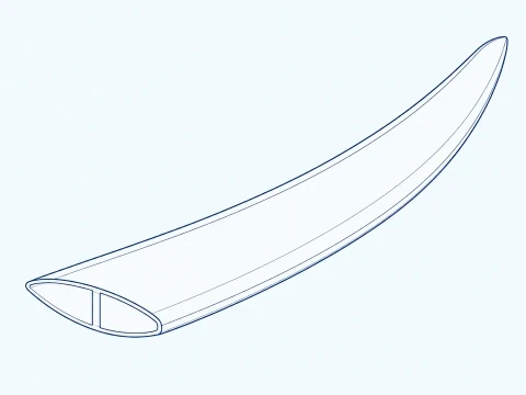
Closed blade section
Two molded halves are bonded into a hollow closed section, with an internal web where the drawing specifies one.
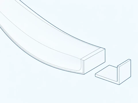
Attachment-ready end
A shaped shell end provides a land for inserts or a separate mating bracket when ordered. Hole positions and load transfer follow your attachment drawing.
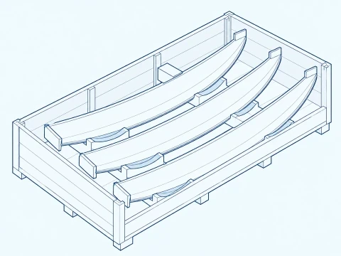
Blade component set
A set of curved components follows the sizes and quantities on your rotor parts list and is packed on padded supports that keep attachment lands clear.
Blade shell profile and end fit
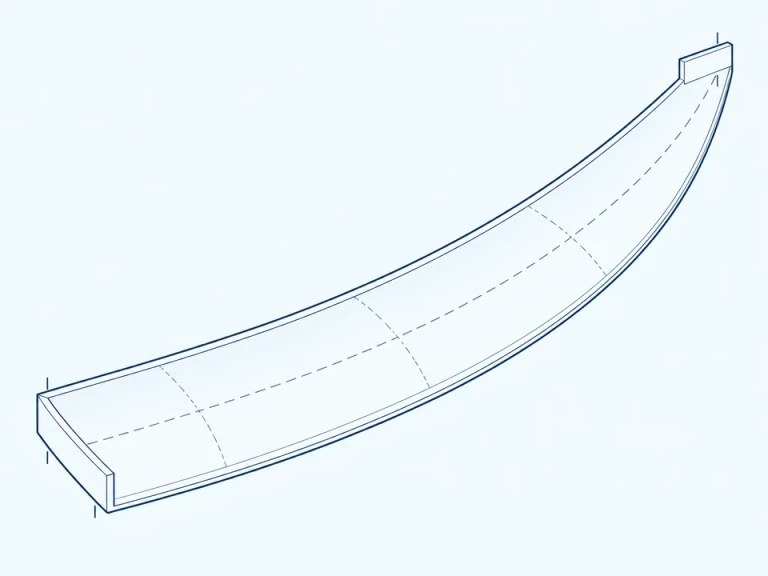
Curved shell and fixing positions
The upper section measures the straight chord between the ends of the curved shell. The elevation measures shell-body height and the spacing between two attachment-hole centers.
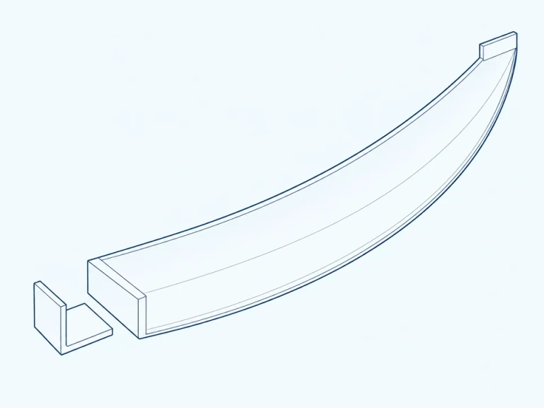
Curved segment and end faces
Returned end faces give a fixing land for the mating bracket. Shell curvature and end geometry follow your blade drawing, and any attachment bracket is specified separately.