Composite Equipment Cover Design for Airflow and Access
Learn how to design composite equipment covers that manage heat, weather, contamination, service access, seals, lifting, and mounting interfaces.
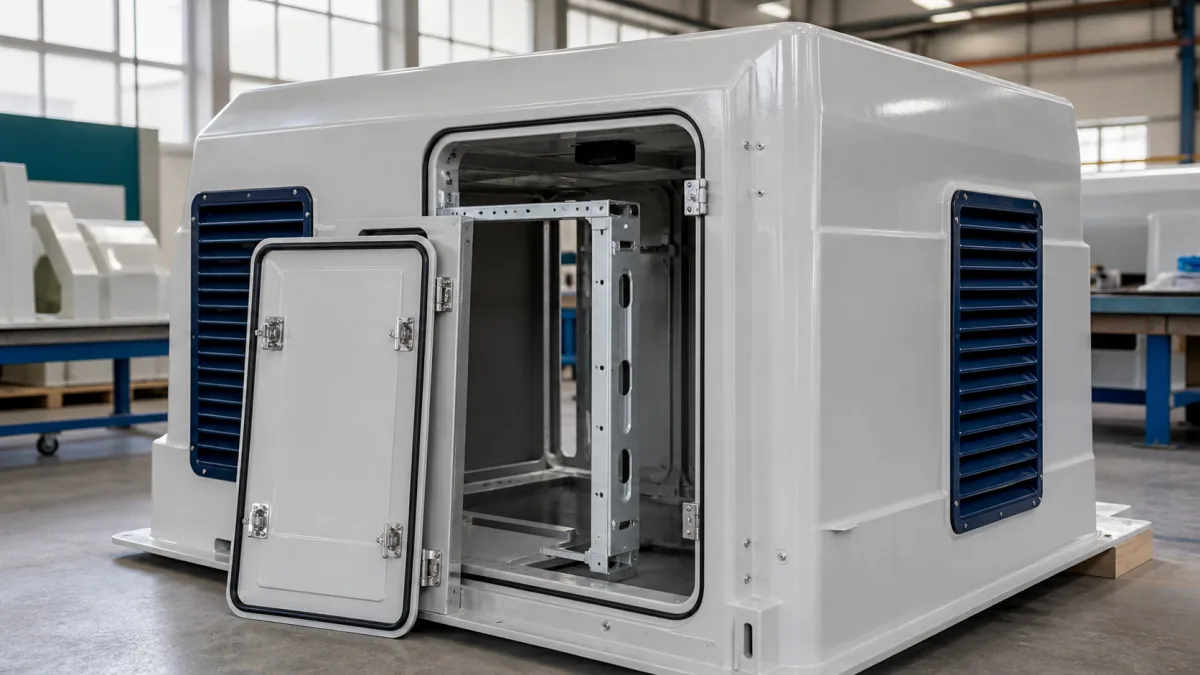
A successful composite equipment cover does more than shield a machine. It creates a controlled boundary around heat, airflow, contamination, weather, noise, controls, and maintenance work. The best design starts with the equipment’s operating and service requirements—not the outside shape of the cover.
For a custom FRP or carbon-fiber cover, document every interface before tooling begins: heat sources, intake and exhaust paths, access points, mounting locations, lifting method, seals, drains, cable entries, and inspection requirements. This approach helps prevent common problems such as overheating, water intrusion, inaccessible fasteners, cracked mounting areas, and panels that are too large to remove safely.
For broader enclosure concepts and construction options, see these industrial equipment enclosures.
Map Equipment Heat and Airflow Paths
Airflow is a system requirement, not simply a matter of adding louvers. A composite equipment cover must allow the equipment to receive adequate cooling air while preventing hot discharge air from circulating back to the intake.
Start by mapping the complete air path:
- Identify each heat-producing component, such as engines, motors, drives, radiators, compressors, transformers, exhaust components, and electronics.
- Mark air intakes, discharge openings, fan directions, and any cooling-air requirements supplied by the equipment manufacturer.
- Identify areas where heated air could become trapped under the cover.
- Separate intake and discharge zones as much as the packaging allows.
- Account for restrictions caused by screens, filters, louvers, duct transitions, and narrow passages.
A cover opening that appears large enough can still restrict airflow if it has a high-pressure-drop louver, a dense screen, or an indirect path. The geometry around an opening matters as much as its nominal size. Avoid placing an intake directly beside an exhaust discharge, especially where wind or nearby walls can push hot air back into the enclosure.
Account for heat near composite surfaces
FRP and carbon-fiber laminates can be engineered for demanding environments, but resin selection, laminate construction, insulation, and air gaps must suit the anticipated temperatures. Do not assume the cover material can contact a hot exhaust pipe, manifold, radiator discharge, or other high-temperature surface.
For each hot zone, define:
- Expected normal and maximum surface or air temperatures
- Distance from the heat source to the composite panel
- Required insulation, shielding, or ventilation gap
- Whether heat is continuous, intermittent, or only present during upset conditions
- Accessible surfaces that personnel may touch during service
Where temperature data is uncertain, treat that as a design input that needs confirmation before finalizing the laminate and internal layout.
Avoid these airflow mistakes
Common failures include locating intake louvers on the same face as hot discharge, enclosing a radiator without adequate discharge area, putting a rain baffle directly in a fan path, and adding filters without allowing for filter loading over time. Another frequent oversight is assuming that a cover tested with doors open will perform the same way with all access panels closed.
A functional prototype or airflow review should represent the actual operating configuration, including installed filters, grilles, doors, and nearby equipment.
Define Contamination and Weather Exposure
The environment determines how the cover should manage water, dust, salt, chemicals, sunlight, washdown, and impact. “Outdoor use” alone is not a sufficient environmental requirement. A rooftop mechanical unit, a quarry machine, a food-processing installation, and a coastal generator enclosure face very different exposure conditions.
Use a concise exposure profile during design review.
| Exposure condition | Design questions to resolve | Typical cover considerations |
|---|---|---|
| Rain and wind-driven water | Which faces receive direct weather? Can water enter through openings? | Hooded openings, overlap joints, drainage paths, protected seams |
| Dust and debris | What particle sources are present? Is cooling air filtered? | Serviceable filters, screens, separated intake areas, cleanout access |
| Salt or corrosive atmosphere | Are metal inserts, hinges, and latches compatible with the environment? | Material compatibility review, isolated interfaces, protected hardware |
| Washdown or splash | What water pressure, direction, and cleaning chemicals are involved? | Defined seal strategy, drainage, protected electrical entries |
| UV exposure | Will the cover receive persistent direct sunlight? | Exterior finish and resin system suited to the exposure requirement |
| Impact and vibration | Can tools, forklifts, stones, or moving parts strike the cover? | Local reinforcement, guards, standoff clearance, repair planning |
Plan water instead of trying to eliminate every opening
Ventilation openings, service doors, hinges, and cable penetrations create opportunities for water entry. A practical weather-resistance strategy manages water in layers:
- Deflect it at the outer surface with hoods, overhangs, and lapped joints.
- Keep water away from sensitive internal components with baffles or separated compartments.
- Drain water that reaches internal channels or low points.
- Avoid horizontal surfaces and enclosed pockets where water can stand.
- Ensure drain paths remain open after the cover is mounted.
Do not place a drain directly above electrical connections, control panels, or areas where discharge could create a slip, corrosion, or freezing issue. Also consider whether an enclosure is expected to withstand only normal rain or more severe washdown conditions; the seal and closure strategy may differ substantially.
Plan Service Doors, Panels, and Removal Clearance
A cover that protects equipment but prevents routine maintenance creates unnecessary downtime and safety exposure. Design access around actual maintenance tasks, not only around what is visible from outside.
Create a service-access map that identifies which tasks require:
- Visual inspection
- Hand access
- Tool access
- Component removal
- Fluid filling or draining
- Filter replacement
- Electrical reset or control adjustment
- Full cover removal
For each task, identify the necessary door, panel, clearance envelope, and opening direction. A small inspection door may be enough for a gauge reading, but a larger removable panel may be required to change a filter or remove a drive component.
Doors, removable panels, and full-shell covers
Each access method has tradeoffs:
| Access approach | Best suited for | Key design concern |
|---|---|---|
| Hinged door | Frequent inspection or routine service | Swing clearance, hinge load, latch compression, door retention |
| Removable panel | Infrequent component access | Fastener access, panel handling, repeatable resealing |
| Lift-off cover | Broad access to compact equipment | Safe lift points, weight, alignment, storage during service |
| Split enclosure | Large equipment or constrained installation areas | Joint sealing, assembly sequence, interface alignment |
A door should open far enough for the intended task without contacting piping, walls, adjacent machinery, or personnel pathways. Confirm clearance in the installed location, not only in a standalone CAD model. For removable panels, specify where the technician will hold the panel, where fasteners will be placed, and whether a dropped fastener could enter the equipment.
Avoid making a panel large simply to reduce part count. Large composite panels can be awkward to handle, difficult to store during maintenance, and vulnerable to damage if unsupported.
Coordinate Seals, Louvers, Filters, and Drainage
Seals, ventilation components, and drainage features need to work together. Treating them as separate add-ons often leads to compressed gaskets beside unprotected louvers, water trapped behind filters, or drains blocked by mounting brackets.
Establish a clear sealing strategy
Define which seams must be sealed, which can be weather-shedding overlaps, and which need to remain open for ventilation or pressure equalization. Seal selection should consider compression range, temperature exposure, chemical exposure, closure force, and expected service frequency.
Ask these questions at each joint:
- Is the joint intended to be dust-resistant, weather-resistant, splash-resistant, or simply covered?
- Will the panel be opened frequently?
- Does the flange provide a continuous, sufficiently stiff sealing surface?
- Are there corners, fasteners, or changes in section that interrupt the seal?
- Can water collect against the gasket or leak path?
A gasket cannot compensate for a warped panel, insufficient flange width, uneven latch loading, or a closure that does not align repeatably. Design the panel edge, latch points, and reinforcement together.
Select louvers and filters by function
Louvers can shed rain and obscure internal components, but they reduce free area and add resistance. Filters protect equipment from contamination but must be accessible for inspection and replacement. Screens help exclude larger debris but may clog in certain operating environments.
Before choosing an intake arrangement, confirm:
- Required airflow at the intended operating condition
- Allowed pressure drop for the equipment
- Type and concentration of expected contaminants
- Filter maintenance interval and replacement procedure
- Whether rain, snow, insects, leaves, or wind-blown debris are relevant
- Whether cleaning can be done without removing the full cover
Provide a clear route for water around—not through—the ventilation system. If a louvered opening includes a baffle or collection channel, make sure collected water can drain without wetting the filter or entering the equipment bay.
Locate Cables, Pipes, Controls, and Viewing Areas
Cable entries, pipe penetrations, control interfaces, and viewing windows should be planned before the cover geometry is frozen. Late changes in these areas often require cutouts that weaken a panel, interfere with seals, or create difficult-to-service connections.
Place penetrations where they can be installed, inspected, and resealed. Consider connector bend radius, cable strain relief, conduit fittings, pipe movement, thermal expansion, vibration, and the wrench clearance needed for assembly.
Protect controls without blocking access
Controls and displays may need protection from weather, impact, and unauthorized contact while remaining readable and operable. Options include a gasketed access door, a recessed control bay, a protected clear viewing area, or an external mounting location.
For viewing areas, define the required line of sight, lighting conditions, condensation risk, cleaning method, and resistance to the operating environment. A viewing window that fogs, scratches, or sits behind a reflective surface may not provide useful inspection access.
Keep cable and pipe penetrations away from low points where water can accumulate. If penetrations must be near a seam, ensure there is enough flat, reinforced area for the selected fitting and sealing arrangement.
Design Mounting, Lifting, and Local Reinforcement
Composite covers need well-defined load paths. Mounting bolts, hinges, latches, gas springs, lifting points, and equipment attachments all introduce localized loads that may require laminate buildup, embedded reinforcement, backing plates, or a dedicated subframe.
Do not treat a thin outer skin as a universal attachment surface. The appropriate solution depends on the load type, direction, frequency, vibration, access to the back side, and environmental exposure.
Review every attachment point
For each mount, identify:
- Static equipment and cover loads
- Dynamic loads from vibration, wind, transport, opening doors, or handling
- Bolt size and required access for installation
- Need for inserts, backing plates, or molded-in reinforcement
- Galvanic and corrosion compatibility of hardware and adjoining materials
- Tolerances between the equipment frame and cover
- Whether the cover carries a load or only serves as a protective shell
Lifting provisions deserve special attention. A lifting feature must be clearly distinguished from a handling grip, and its intended use must be defined. If the cover is to be lifted separately, confirm lifting orientation, balance, attachment locations, rigging clearance, and whether doors or removable components must be secured first.
Avoid relying on an unverified panel edge, louver frame, or service-door hardware as a lifting location.
Prototype Fit, Ventilation, and Maintenance Tasks
A prototype is most valuable when it tests the decisions that are difficult or expensive to correct after molded production begins. The objective is not just to confirm that the cover looks correct; it is to verify fit, function, assembly, and serviceability.
Use a prototype review to check:
- Equipment fit: Confirm mounting points, interference zones, panel gaps, and tolerance stack-up.
- Airflow layout: Inspect the complete intake and discharge path with final-style louvers, filters, and internal barriers.
- Door operation: Open every service door and remove every panel in the actual installation orientation.
- Maintenance tasks: Perform representative filter changes, inspections, fluid service, and component-access steps.
- Water management: Verify that seams, louvers, gutters, and drains direct water away from sensitive areas.
- Handling: Confirm that removable components can be safely lifted, carried, and reinstalled.
- Hardware access: Check that tools can reach fasteners, latches, hinges, and cable fittings.
Common prototype discoveries include a filter that cannot clear a frame, a door blocked by a pipe, a cable connector with inadequate bend space, or a drainage channel that terminates at a mounting bracket. These are exactly the issues worth identifying before final tooling.
For applications such as standby power equipment, a custom FRP generator canopy may require an especially detailed review of ventilation, exhaust separation, access, and weather protection.
Release Interfaces and Inspection Criteria
A production-ready cover package should define what the supplier is building and how the finished part will be evaluated. A drawing with exterior dimensions alone is not enough for a functional equipment enclosure.
Release documentation should cover:
- Overall envelope and critical clearance dimensions
- Equipment mounting interfaces and allowable tolerances
- Cutouts, vents, penetrations, and hardware locations
- Door and panel operation requirements
- Material, finish, color, and appearance expectations
- Required inserts, reinforcements, and attachment hardware
- Seal and drainage details
- Defined inspection references, including datum points or a master fixture where applicable
- Acceptance criteria for fit, visible surfaces, and functional operation
- Packaging and shipment handling requirements where relevant
Separate critical dimensions from cosmetic preferences
Not every dimension requires the same control level. Clearly identify the dimensions that affect equipment fit, sealing, door alignment, airflow components, and mounting. Likewise, distinguish visible appearance zones from hidden internal surfaces. This helps focus inspection on the features that affect function and avoids ambiguity during quoting and production.
For custom composite work, GFIND can support projects from buyer drawings and application requirements through manufacturability review, tooling, prototypes, molded production, finishing, inspection to agreed references, and shipment preparation. The quality of the initial interface package directly affects how effectively those steps can be coordinated.
Build a Better RFQ for a Composite Equipment Cover
Before requesting a quote or design review, assemble the following:
- Equipment drawings, 3D models, or measured interface dimensions
- A heat-source and airflow diagram
- Environmental exposure description
- Required service tasks and access frequency
- Photos of the installed equipment and surrounding clearance constraints
- Preferred opening, lifting, and mounting methods
- Hardware, cable, piping, and controls information
- Appearance, finish, and color requirements
- Prototype expectations and final inspection criteria
- Expected order quantities, if known
The strongest composite equipment cover design balances protection with practical operation: it keeps heat moving, contaminants managed, water draining, and service tasks accessible. If you have an equipment layout or preliminary drawing, contact GFIND to discuss manufacturability and the inputs needed for a custom composite cover.