Custom FRP Facade Panel Planning for Reliable Installation
Plan custom FRP facade panels with clear geometry, joints, supports, finishes, mockups, and installation responsibilities for a buildable exterior.
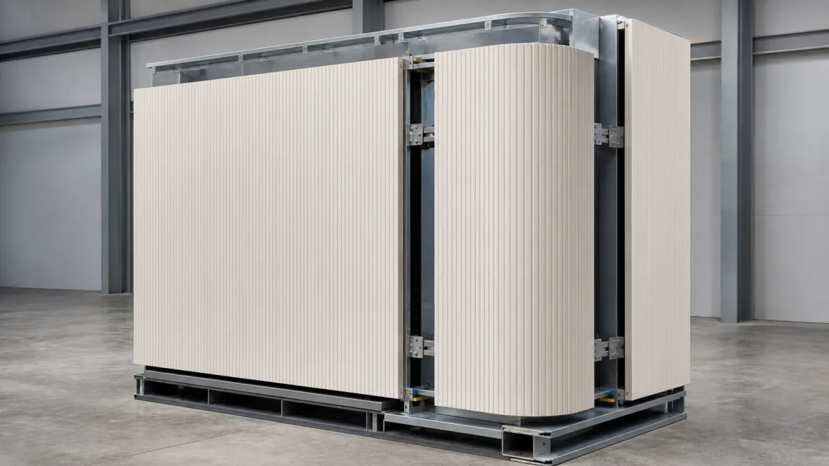
Custom FRP facade panel planning should begin before a fabricator prices the work. The team needs a coordinated basis for panel geometry, support conditions, joint behavior, finish expectations, installation access, and responsibility boundaries. A visually compelling rendering alone is not enough to define a buildable facade.
For custom composite cladding, the most useful RFQ package identifies what must remain visually continuous, where panels may divide, how the panels attach to the building, and which project party owns engineering decisions. Early coordination reduces the risk of impractical panel sizes, mismatched interfaces, difficult field adjustments, and appearance disputes after installation.
For projects involving nonplanar forms, review curved FRP facade panel options alongside the architectural geometry before finalizing panel breaks.
Start with Design Intent and Building Constraints
Define the facade’s intended appearance before selecting panel shapes or fabrication methods. Identify the visual priorities: continuous curvature, shadow lines, recessed joints, repeating modules, deep reveals, integral trim, or a seamless monolithic appearance. Rank these priorities, because some can conflict with transport, access, support spacing, or field installation needs.
The design package should include more than elevations. Useful inputs include:
- Dimensioned plans, elevations, sections, and details
- A current 3D model in an agreed file format
- Surface-control geometry for curved or freeform areas
- Panel zones and proposed joint locations
- Design wind pressures and other relevant loading criteria
- Wall assembly, insulation, air/water barrier, and cavity requirements
- Available backup structure and attachment locations
- Openings, penetrations, louvers, doors, signage, and building movement joints
- Access limitations for cranes, lifts, staging, and panel handling
Clarify whether FRP panels are architectural cladding, a rainscreen element, an enclosure component, or part of a broader facade assembly. That distinction affects who designs the subframing, flashing, drainage path, fire-performance approach, and connections to adjacent trades.
Building constraints often establish the real limits of a panel scheme. A large uninterrupted panel may look ideal in a visualization but be difficult to transport, lift, turn around corners, or align on a structure with normal construction variation. Conversely, very small panels can create excessive joints, attachment points, and installation labor.
Discuss the project’s environmental exposure early. Sun intensity, temperature cycling, moisture, airborne pollutants, coastal conditions, and cleaning methods can all influence resin selection, finish strategy, joint design, and maintenance planning. The project team should define performance requirements rather than assume a generic FRP formulation will suit every exposure.
Create a Manufacturable Panelization Strategy
Panelization converts the design surface into repeatable, buildable units. A good strategy balances appearance, mold and fabrication practicality, shipping dimensions, lifting weight, support locations, and manageable field adjustment.
Start by dividing the facade into logical visual zones. Panel boundaries may align with floor lines, columns, window mullions, reveals, corners, parapets, or intentional shadow gaps. Where a joint cannot be concealed, make it deliberate. A consistent reveal is usually more controllable than a joint placed arbitrarily through a smooth feature.
For each proposed panel, review these questions:
| Planning factor | What to decide | Common risk if unresolved |
|---|---|---|
| Panel extent | Maximum length, width, depth, and projected area | Panels cannot be handled, transported, or safely maneuvered |
| Curvature | Single-axis, compound, or freeform geometry | Surface may not match the intended visual continuity |
| Repetition | Which panels share identical geometry | Unnecessary tooling or inconsistent appearance |
| Edge conditions | Returns, corners, and transition pieces | Visible seams, weak edges, or inaccessible fasteners |
| Attachment zones | Locations for brackets or embedded reinforcements | Conflicts with structure, insulation, or joints |
| Field access | Reach for fasteners, shims, and sealant | Installation sequence becomes impractical |
Do not assume that every visually similar panel is geometrically identical. On a curved facade, small changes in radius, twist, or return depth can make a panel unique. The design team should identify true repeats in the model and distinguish them from nominally similar pieces. This improves tooling decisions and helps procurement compare scope accurately.
Large panels can reduce visible joints, but they are not automatically the best solution. They may require more complex handling, more robust support arrangements, and tighter coordination with the installer. Smaller panels can be easier to move and replace but introduce more joint lines and more opportunities for cumulative alignment error.
A practical panel schedule should assign a unique mark to every panel type and show quantity, nominal dimensions, orientation, revision status, finish, and special features. For highly variable geometry, include a model-based schedule or coordinate table rather than relying only on scaled drawings.
When evaluating suppliers, ask how they will review manufacturability against the design intent. GFIND can work from buyer drawings and application requirements and may support manufacturability review, tooling, prototypes, molded production, finishing, inspection to agreed references, and shipment preparation. The project still needs to establish who approves final geometry and interfaces.
Coordinate Joints, Returns, and Support Interfaces
Joints are both visual features and movement-management details. They must accommodate panel installation, normal construction tolerances, thermal movement, drainage, sealant geometry where applicable, and access for maintenance or replacement.
Specify the intended joint type rather than labeling every gap simply as “sealant.” Typical approaches may include open rainscreen joints, gasketed joints, sealant joints, expressed reveals, overlapped edges, and mechanically covered joints. Each has different requirements for cavity depth, backing conditions, water management, visual consistency, and installer access.
Returns deserve the same attention as front faces. A panel edge wrapping into a window opening, corner, soffit, or parapet needs enough depth and stiffness for the intended attachment and enough clearance to avoid clashes with adjacent assemblies. Deep returns may need intermediate support or a separate trim strategy.
Coordinate these interface questions:
- Is the attachment concealed, exposed, or a combination of both?
- Does the panel attach directly to backup structure or to secondary rails?
- Who provides clips, brackets, fasteners, shims, and isolation materials?
- Can fasteners be reached after adjacent panels are installed?
- Are attachment points located away from unsupported thin edges?
- How will the facade accommodate building expansion joints?
- What prevents galvanic or moisture-related incompatibility between materials?
- Where do flashings, drainage planes, and air/water barrier transitions occur?
A frequent mistake is designing an attractive panel face without leaving a workable load path behind it. FRP cladding should not be expected to solve an undefined structural connection. The facade engineer or other responsible design professional should determine connection demands, backup assumptions, and load transfer based on the project’s governing criteria.
For broader concept examples, review architectural FRP facade panel solutions while keeping project-specific interfaces subject to detailed coordination.
Set Datums, Tolerances, and Survey Inputs
Facade tolerances should be agreed before fabrication, not negotiated during installation. Custom FRP panels can be made to approved references, but no panel system can compensate indefinitely for unknown or inconsistent field conditions.
Establish a shared coordinate system and identify the primary datums. These may include grid lines, finished floor elevations, slab edges, column centerlines, control points, and a facade setting-out line. Every discipline should work from the same references in the current model and drawings.
The team should document:
- Which model or drawing revision controls fabrication
- The authorized coordinate origin and elevation datum
- Expected tolerances for backup structure and secondary framing
- Permitted panel face variation, joint-width variation, and alignment offsets
- Measurement methods and units
- Required field survey deliverables before release to production
- The process for handling deviations found after survey
Do not use a generic tolerance number without considering the panel size, reveal width, finish reflectivity, and viewing distance. A small variation may be visually obvious at a narrow, high-contrast shadow joint even when it is structurally inconsequential. Similarly, a glossy dark finish can reveal waviness more readily than a textured, low-gloss surface.
For complex geometry, a pre-installation survey of the installed backup or support frame is especially valuable. Compare the survey to the coordinated design model, identify deviations, and decide whether adjustment belongs in brackets, subframing, shims, panel geometry, or local site correction. Fabricating to unverified theoretical geometry is a common source of field rework.
Approve Color, Texture, Gloss, and Weathering Strategy
Finish selection is a performance and maintenance decision, not only an aesthetic one. The specification should identify the approved color reference, texture, gloss range, viewing conditions, acceptable variation, repair expectations, and weathering approach.
Color names alone are not sufficient. “Charcoal,” “bronze,” or “white” can vary substantially by pigment, gloss, texture, lighting, and adjacent materials. Provide physical reference samples or a clearly defined color standard where possible. Then evaluate the finish under expected daylight and artificial lighting, not solely in a design studio.
Consider the following finish factors:
- Color consistency: Define how different panel lots, orientations, and adjacent materials will be compared.
- Gloss level: Higher gloss may increase visual sensitivity to surface irregularities and reflections.
- Texture: Texture can support the design intent and reduce the prominence of minor visual variation, but it must be repeatable across panels.
- UV and exposure conditions: Confirm the intended exterior exposure and the selected finish system’s suitability for it.
- Cleaning: Identify anticipated cleaning chemicals, abrasion, graffiti-removal methods, and access constraints.
- Repairability: Decide how chips, scratches, or field modifications will be addressed and approved.
- Aging expectations: Agree on what level of normal color or gloss change is acceptable over time.
Avoid approving finishes from a small coupon alone when the facade includes large smooth panels, dramatic curvature, or complex lighting. The same finish can look different across a broad area or at changing angles. A representative mockup provides a more reliable basis for appearance decisions.
Use Mockups for Appearance and Interface Review
A mockup is the most efficient way to find problems that drawings and renderings do not reveal. It should be treated as a decision-making tool, not merely a display piece.
The scope can range from finish samples to a full-scale assembly. For a complex facade, a useful mockup may include representative panel geometry, joints, returns, attachments, subframing, insulation, flashing, openings, transitions to other cladding, and the intended installation sequence.
Before building it, define what the mockup must answer. Typical review criteria include:
- Does the panel geometry read as intended from normal viewing distances?
- Are joint widths, shadow lines, and corners visually consistent?
- Can installers access clips, fasteners, shims, and sealant locations?
- Do panels align with windows, louvers, and adjacent facade materials?
- Are drainage and flashing transitions clear?
- Does the finish meet approved color, texture, and gloss expectations?
- Can the assembly be inspected and repaired in a realistic manner?
Record approvals and unresolved items in writing. If the mockup establishes an accepted visual standard, identify where it will be retained, how it will be protected, and which features are binding for production comparison. A mockup does not replace project engineering, testing, or code review; it helps the team validate the proposed assembly before committing to full production.
Plan Packing, Lifting, and Installation Sequence
Transport and handling requirements can directly affect panel design. Confirm packaging, lifting points, support orientation, delivery access, site storage, and installation sequencing before panels are finalized.
Custom FRP panels should be packed to protect finished faces, edges, corners, and projecting returns. The packing method must also allow site personnel to identify panel marks and remove pieces in the planned order without repeatedly moving unrelated panels.
The installation plan should address:
- Maximum allowable lift size and weight for available equipment
- Approved lifting locations and any spreader-bar requirements
- Protection against flexing, twisting, or point loading during handling
- Delivery sequence by elevation, zone, or panel mark
- Site storage orientation, weather protection, and access
- Safe removal of packaging without damaging finishes
- Temporary supports and final fastening sequence
- Inspection hold points before adjacent panels conceal interfaces
Never assume a panel can be lifted from any edge or by an improvised attachment. Lifting methods should be established for the specific panel design and coordinated with the installer’s means and methods. Similarly, do not leave replacement planning until after completion. Identify whether future panel removal is possible without dismantling large areas of surrounding work.
Assign Engineering and Compliance Responsibilities
Clear responsibility assignment is essential because a facade combines architecture, structural support, enclosure performance, code requirements, fabrication, and installation. A custom FRP panel manufacturer can provide fabrication-related input, but project professionals must define the governing design and compliance requirements.
Create a responsibility matrix that identifies who is accountable for:
| Scope item | Responsibility to assign |
|---|---|
| Architectural appearance and panel layout | Design team |
| Structural loading criteria and backup assumptions | Responsible engineer |
| Connection and subframing design | Assigned engineer or specialty designer |
| Water management and enclosure interfaces | Facade/enclosure design team |
| Material, finish, and visual approval | Owner and design team |
| Fabrication drawings and production references | Fabricator, subject to defined review process |
| Field measurement and survey verification | Assigned contractor or survey party |
| Installation means, methods, and site safety | Installer/contractor |
| Applicable code, fire, and project compliance path | Responsible project professionals |
Requirements involving fire behavior, structural performance, wind resistance, water penetration, or other code-related issues should be evaluated for the specific building assembly and jurisdiction. Do not assume that material-level information alone demonstrates compliance for a complete wall system. Confirm which tests, reports, calculations, submittals, or authority approvals the project requires—and who will provide or review them.
A complete RFQ should include the latest geometry, panel schedule, finish expectations, quantity, support concept, interface details, delivery constraints, inspection references, and the desired commercial scope. If drawings are still developing, identify the open decisions rather than presenting assumptions as final requirements.
When your team is ready to discuss a defined panel concept or request a manufacturability review, contact GFIND with the available drawings, model information, finish references, and installation assumptions.