Custom FRP First Article Inspection: A Review Guide
Use a disciplined custom FRP first article inspection to verify fit, dimensions, laminate records, finish, deviations, and production release controls.
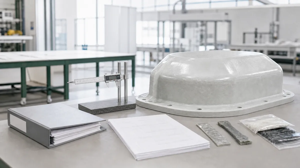
A custom FRP first article inspection is the structured review of an initial production-representative part before repeat manufacturing begins. Its purpose is not simply to decide whether the part “looks good.” It verifies that the part matches the approved drawing and specification package, fits its mating components, meets agreed functional and cosmetic requirements, and has a documented baseline for future orders.
The most effective review combines dimensional inspection with real-world fit checks, laminate and process record review, visual evaluation, and formal disposition of every deviation. A part can pass a basic measurement check yet still create assembly, hardware, sealing, or appearance problems later. Reviewing the first article as a complete system reduces that risk.
Confirm the Approved Reference Package
Start by confirming exactly what the first article is being judged against. Many first-article disagreements stem from mismatched files, incomplete drawings, informal email changes, or an assumption that a prototype detail automatically applies to production.
The approved reference package should identify the current revision of every item that controls the part, including:
- Part drawing, 3D CAD model, or controlled dimensional layout
- Material and laminate requirements, where specified
- Surface finish, color, texture, gloss, or cosmetic-zone requirements
- Trim, edge, hole, cutout, and hardware requirements
- Mating-part drawings or interface samples
- Inspection criteria, acceptance limits, and measurement method where relevant
- Approved deviations, clarifications, or change notices
- Packaging, labeling, and handling requirements if they affect part condition
If the 3D model and 2D drawing conflict, establish which source governs before accepting or rejecting the part. For fiberglass components, the drawing should also make clear whether dimensions apply to a molded surface, a trimmed edge, a drilled hole center, or a post-machined feature. Those are not interchangeable references.
Define what “first article” means for the project
A first article may be a hand-finished prototype, a tooling trial part, or the first piece made with intended production tooling and procedures. These stages have different purposes.
| First-piece stage | Main question it answers | Caution |
|---|---|---|
| Prototype or development sample | Does the design fit and function as intended? | It may not represent final tooling, finish, or repeatability. |
| Tooling trial part | Does the tool produce the correct form and surface? | Trimming and process settings may still be adjusted. |
| Production-representative first article | Can the agreed process make an acceptable repeatable part? | It should be tied to the approved production baseline. |
Buyers should define the intended stage in the purchase order or first-article plan. Do not assume that approving an early development sample automatically releases repeat production.
Inspect Critical Dimensions and Datums
First-article dimensional inspection should focus first on characteristics that control assembly, function, safety, sealing, or downstream fabrication. A complete report may include many measurements, but not every dimension carries the same risk.
Begin with the datums. Datums establish how the part is located during measurement and how it will be located in its assembly. If the inspection fixture, coordinate system, or part orientation differs from the design intent, a technically accurate measurement can still be misleading.
For a custom fiberglass part, critical characteristics commonly include:
- Overall length, width, height, and profile
- Mounting-hole locations and diameters
- Cutout size and placement
- Flange width, flatness, and mating-surface location
- Centerlines, symmetry, and angular relationships
- Standoff, rib, boss, or reinforcement locations
- Bonded insert position and depth
- Edge-to-hole distances
- Curvature or contour at a mating interface
Record the actual measurement, the specified requirement, the allowed tolerance, the method used, and the part’s acceptance status. A simple “pass” designation is less useful than a value that can be reviewed if a later assembly issue occurs.
Use measurement methods appropriate to the feature
A tape measure may be reasonable for a noncritical overall shipping envelope but is not appropriate for a precision hole pattern. Likewise, a handheld caliper may not characterize a large, contoured FRP panel adequately.
Choose a method that fits the feature and the tolerance. Depending on the part, this may include:
- Inspection fixtures or go/no-go gauges for repeated interfaces
- Calipers, height gauges, or pin gauges for localized features
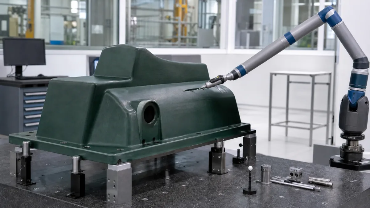
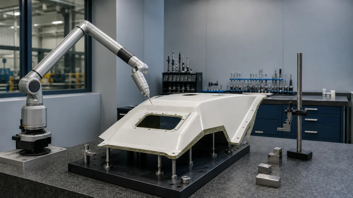
- Coordinate measurement or scanning for complex profiles
- Template checks for contour or trim verification
- Assembly checks using actual mating components
The first-article plan should identify whether dimensions are measured free-state, supported in a fixture, or installed in an assembly. Thin composite panels can flex under their own weight or during handling. A free-state measurement and an installed measurement may both be valid, but they answer different questions.
A common mistake is measuring only the dimensions that are easy to reach. Critical locations may be inside flanges, around openings, or on a contoured surface where fixturing and datum setup matter most.
Test Fit Interfaces, Openings, and Hardware
Dimensional data is essential, but it does not replace a physical fit test. Where possible, mate the first article to the actual production interface, a controlled fixture, or a representative assembly.
Check the part in the orientation and sequence expected during installation. This can reveal interference, limited tool access, clamp-up distortion, or a fastening sequence that was not apparent in CAD.
Review these interface conditions:
- Alignment with frames, brackets, panels, housings, or support structures
- Clearance around adjacent parts throughout the operating position
- Hole alignment with bolts, fasteners, clips, or inserts
- Access for tools, washers, nuts, and installation hands
- Fit of doors, lids, seals, gaskets, louvers, or removable covers
- Contact and gap consistency along flanges or mating edges
- Stability under normal mounting loads
- Routing clearance for cables, hoses, or other nearby components
For molded-in or bonded inserts, confirm thread type, location, engagement depth, pull-through support, and any required isolation from dissimilar materials. If the interface includes metal hardware, define torque requirements and test conditions where they are relevant to the design. Over-tightening can damage a composite laminate even when the mounting hole is dimensionally correct.
Evaluate openings as functional features
Openings deserve more than a width-and-height check. Evaluate their edge condition, radius, orientation, and accessibility. A cutout that meets nominal dimensions may still interfere with a connector, gasket, latch, or service tool because of corner geometry or part curvature.
For parts exposed to weather, dust, moisture, or washdown conditions, confirm that sealing interfaces and drainage features work as designed. The first article is the right time to find an inadequate flange width or a gap that prevents a gasket from seating properly.
Review Laminate and Process Records as Agreed
A first article review should verify agreed laminate and process information, but the scope should be defined before production starts. Not every custom FRP order requires the same level of documentation.
For example, a buyer may request confirmation of the specified reinforcement type, resin system, core material, ply schedule, local reinforcements, or insert placement. Other projects may require only a material declaration and visual confirmation because the part is nonstructural.
The review package can include, as applicable:
- Material identification for reinforcement, resin, core, gel coat, or coatings
- Laminate schedule or layup reference
- Records for localized reinforcements and embedded components
- Cure, post-cure, or process records when specifically agreed
- Tooling and process reference used for the first article
- Part identification or traceability information
- Any agreed test coupon, sample, or verification result
The key is to compare records to the approved requirements, not to impose unstated criteria after the part is made. A visual inspection cannot prove all internal laminate details, and a process record does not replace a required structural or functional test. Use the methods specified for the part’s risk level.
If a design calls for a particular fire performance, chemical resistance, electrical property, load rating, or environmental capability, those requirements should be stated clearly in the reference package along with the required verification method. Do not infer those properties solely from the general term “fiberglass.”
Evaluate Visible Surfaces and Edge Quality
Appearance review should separate cosmetic requirements from ordinary molded-part variation. FRP parts can have different acceptable finish levels depending on whether the surface is customer-facing, painted, enclosed, or purely functional.
Define visible surfaces and viewing conditions before inspection. A cosmetic exterior panel may require a controlled color and texture match, while a concealed structural bracket may permit surface evidence that would be unacceptable on a finished enclosure.
Inspect agreed cosmetic zones for:
- Color consistency and coverage
- Gloss, texture, and surface uniformity
- Print-through, waviness, or sink-like appearance
- Voids, pinholes, blisters, cracks, or exposed reinforcement
- Mold-release residue or contamination
- Scratches, handling marks, and finish damage
- Flash, sharp edges, rough trim, or uncontrolled fibers
- Edge sealing or coating where specified
Check edges carefully around trim lines, holes, and cutouts. Rough edges can create handling hazards, interfere with seals, initiate damage, or complicate assembly. A clean edge does not always mean every fiber is invisible; it means the edge meets the agreed finish and safety requirement for its intended use.
Avoid subjective acceptance decisions
Terms such as “smooth,” “good finish,” and “minor cosmetic defect” are open to interpretation. For visible parts, establish practical acceptance criteria using approved samples, photos, defined cosmetic zones, or written limits. The first article is an ideal time to create this visual standard.
Inspect the part under lighting that reasonably represents the intended environment. An unusually harsh inspection light may expose marks that would never be visible in use, while poor lighting can hide meaningful defects. The goal is a consistent, agreed evaluation—not an arbitrary standard applied after manufacturing.
Record Deviations and Corrective Actions
Do not treat deviations as informal discussion points. Every variance from the approved package should be documented, evaluated, and given a disposition.
A useful deviation record identifies:
- The part number and revision
- The affected feature or requirement
- The specified condition and actual condition
- Inspection evidence, such as measured value or photo
- The potential effect on fit, function, appearance, or installation
- Proposed correction, repair, use-as-is request, or design change
- Responsible reviewer and approval status
- Whether the change affects tooling, process instructions, or future inspections
Not every deviation requires scrapping a first article. Some can be accepted through a controlled concession when they have no unacceptable effect on the application. Others may call for a drawing revision because the original requirement was impractical or did not reflect the intended assembly condition.
However, “acceptable for this sample” should not become an undocumented production standard. If a deviation is accepted, state whether it applies only to the inspected part, to a specified lot, or to future production after a formal revision.
Separate correction from corrective action
Correcting the immediate part issue and preventing recurrence are different tasks.
For example, re-trimming an opening may correct one part. The corrective action may require revising a trim fixture, clarifying a drawing datum, adjusting the tool, or adding an in-process check. The first-article review should identify which type of action is needed before approving repeat orders.
Avoid approving a part with the promise that an issue will “be fixed later.” Close the loop with evidence: a revised drawing, updated tool, reinspection result, approved waiver, or another documented action appropriate to the issue.
Protect the Approved Production Baseline
Once the first article is accepted, preserve the conditions that made it acceptable. The approved production baseline is the set of controlled references used to make and inspect repeat parts.
Depending on the project, the baseline may include:
- Approved first-article inspection report
- Released drawing and CAD revision
- Approved physical sample or retained reference part
- Tooling identification and trim fixture reference
- Laminate and material references
- Finish standard, color sample, or cosmetic boundary definition
- Inspection plan and critical-feature checklist
- Packaging and handling instructions
- Approved deviation records and expiration limits
A retained first article can be valuable for comparison, especially where surface texture, contour, or trim appearance is difficult to communicate in a drawing. It should be clearly labeled with the part number, revision, date, and approval status so it is not mistaken for an uncontrolled sample.
Remember that composites can exhibit normal process variation, particularly in large molded or hand-finished shapes. The production baseline should identify the features that must remain tightly controlled while acknowledging any agreed variation that does not affect use.
Release Repeat Orders With Clear Revision Control
A first article should lead to a controlled production release, not merely a verbal approval. The repeat-order package should identify the exact revision that was approved and what, if anything, changed after inspection.
Before releasing repeat production, confirm:
- The accepted first article is linked to the current part number and revision.
- All deviations have a formal disposition.
- Required tooling, trim, laminate, and finish changes are complete.
- Critical dimensions and inspection methods are defined for ongoing checks.
- Interface parts and hardware specifications are current.
- Packaging requirements protect cosmetic and functional features.
- The purchase order references the approved technical package.
A new first article, partial reinspection, or targeted validation may be appropriate when there is a meaningful change to tooling, laminate construction, material source requirement, finish, geometry, trim method, critical hardware, or mating interface. The needed level of review depends on the change and the part’s application risk.
For sourcing teams, it helps to ask suppliers how they will connect the approved first article to repeat production records. GFIND can support projects from drawing review and tooling through molded production, finishing, inspection to agreed references, and shipment preparation. Review its custom composite manufacturing solutions when defining a project’s production scope.
First-Article Review Checklist for Buyers
Use this short checklist before signing off on a custom fiberglass first article:
- Is the drawing, model, and specification revision clearly identified?
- Are datums and measurement conditions aligned with the part’s assembly condition?
- Have all critical dimensions, hole patterns, and cutouts been measured?
- Has the part been test-fitted to actual or representative mating components?
- Are hardware access, fastener engagement, seals, and clearances acceptable?
- Have agreed laminate, material, and process records been reviewed?
- Does the finish meet the requirements for each cosmetic zone?
- Are edges, trim, and openings safe and suitable for installation?
- Is every deviation documented with an approved disposition?
- Has a baseline been established for repeat production and future revision control?
A disciplined custom FRP first article inspection gives engineering, quality, and procurement teams a shared approval point before production volumes increase. For a new RFQ, provide the controlled drawing package, intended application, critical interfaces, material or finish requirements, and the level of first-article documentation required. If you need help framing those inputs, contact GFIND to discuss the part requirements and review approach.