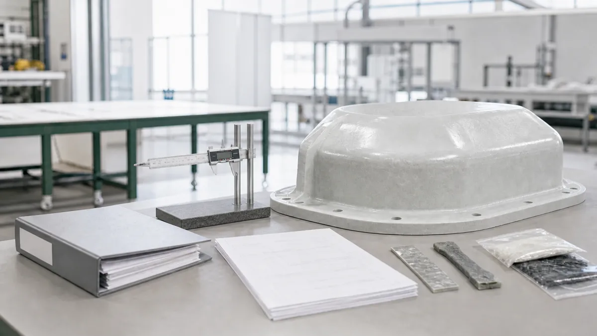
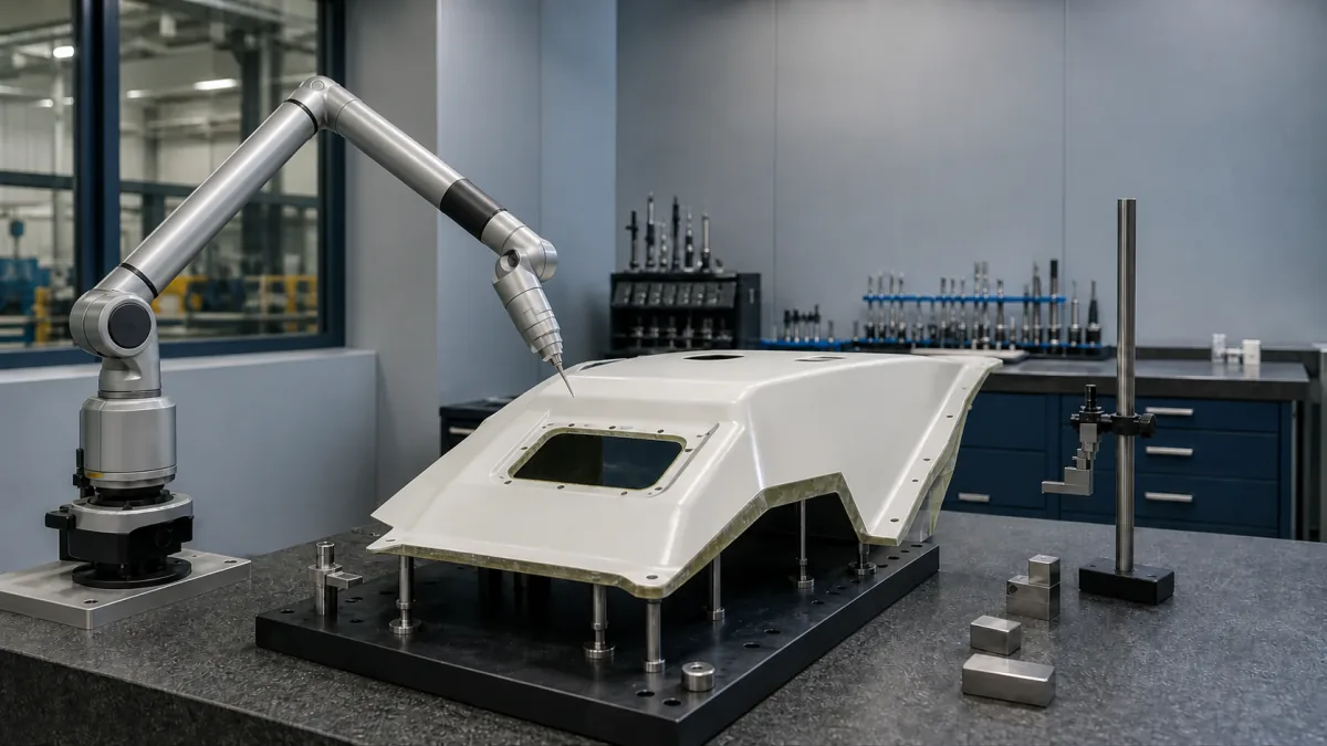
Molded FRP Part Tolerances: A Practical OEM Guide
Learn how to specify practical molded FRP part tolerances, datums, trims, holes, appearance, and inspection criteria before tooling release.
Molded FRP part tolerances should be based on how the part functions in its finished assembly—not on a blanket tolerance applied to every dimension. A fiberglass component can be lightweight, durable, and repeatable, but molding, curing, trimming, and secondary operations each affect which dimensions can be controlled most closely.
The practical approach is to identify the few dimensions that drive fit, sealing, alignment, load transfer, or hardware installation; establish datums that reflect the assembly; and define how each critical feature will be measured. Doing this before tool release helps avoid unnecessary cost on noncritical features while protecting the dimensions that matter.
Distinguish Functional and Cosmetic Requirements
Start by separating requirements that affect assembly or performance from requirements that affect appearance. These categories often need different controls, acceptance criteria, and inspection methods.
Functional requirements are dimensions or conditions that influence whether the part performs its intended job. Typical examples include:
- Mounting-hole locations and diameters
- Flatness at a gasket, flange, or bonded interface
- Clearance around mating equipment
- Part-to-part alignment features
- Insert positions
- Critical overall dimensions needed to fit an enclosure or frame
- Thickness in a load-bearing, insulating, or sealing area
Cosmetic requirements concern visible appearance rather than fit or mechanical function. Examples include:
- Surface texture consistency
- Color variation
- Print-through from reinforcement
- Minor waviness or mold marks
- Edge appearance after trimming
- Gel coat coverage
- Visibility of seams, flash, or repair areas
Do not assume cosmetic surfaces require the tightest dimensional tolerances. A highly visible cover may need strict limits for gloss, texture, and color match, while its non-mating perimeter can allow a more practical trim tolerance. Conversely, a hidden internal panel may need tightly controlled holes or interface faces even if its general appearance is not important.
A useful drawing practice is to label critical features by function. For example:
| Feature | Functional question to answer | Typical control approach |
|---|---|---|
| Mounting holes | Will bolts line up with the mating structure? | Locate from assembly datums; specify positional requirements |
| Perimeter trim | Does the edge need to seal, clear, or simply look finished? | Dimension from datums; identify critical trim segments |
| Flange | Does it contact a gasket or adjoining part? | Define flatness/profile and contact area |
| Outer skin | Is it visible to the end user? | Define surface class and viewing conditions |
| Reinforced zone | Does it carry a load or receive fasteners? | Define laminate, thickness, and hardware requirements |
This distinction makes RFQs clearer. It also prevents a common mistake: calling every dimension “critical” without explaining why. When everything is critical, the supplier has no basis for prioritizing tooling, process controls, or inspection effort.
Choose Datums That Match the Assembly
Datums should represent the way the molded FRP part locates in the real product. The best datum scheme usually comes from the mating assembly, not from whichever molded surface seems easiest to dimension on a drawing.
For a panel that mounts to a steel frame, the primary datum may be the mounting face that contacts the frame. A secondary datum may be a locating edge or feature that establishes left-to-right position. A tertiary datum may prevent rotation. Holes, cutouts, and external boundaries can then be located relative to those references.
A typical three-datum strategy is:
- Primary datum: The surface that establishes the main seating plane.
- Secondary datum: A perpendicular edge, centerline, or locating feature that controls one direction.
- Tertiary datum: A second edge, hole, or feature that establishes orientation.
This approach is especially important for irregular composite shapes. Molded outer surfaces, cosmetic contours, and hand-trimmed edges may not provide stable reference points for functional measurements. If a part is inspected from a nonfunctional surface, it can appear within drawing limits while still failing to fit its mating hardware.
When setting datums, confirm the following:
- Which surfaces actually contact adjacent components?
- Does the part locate on holes, pins, flanges, edges, or a formed pocket?
- Are assembly fixtures based on the same references?
- Will the part be checked free-state, clamped, or installed?
- Does a flexible molded shape need support during measurement?
- Are the datum surfaces accessible after trimming and finishing?
For complex parts, a simple drawing may not communicate all expectations. A 3D CAD model with defined datum features, inspection sections, and clearly identified critical dimensions can reduce interpretation issues. The model should not replace the drawing unless the purchase documentation clearly states which source controls dimensions and revisions.
Set Tolerances Around the Molding Process
Molded FRP is not machined aluminum, and it should not be toleranced as though every surface will behave like a rigid precision-machined feature. Composite parts can be influenced by mold condition, resin system, reinforcement architecture, part geometry, cure behavior, demolding, trimming, and post-mold operations.
The appropriate tolerance depends on the feature and process used to create it.
Features formed directly by stable tooling are generally the best candidates for closer control. Examples include molded contours, molded ribs, defined flanges, and features that are fully supported by the mold. Features created later—such as trim edges, drilled holes, routed cutouts, bonded brackets, or installed inserts—require their own process and reference strategy.
Instead of applying one default plus-or-minus value across an entire drawing, classify dimensions according to their function and manufacturing path:
- Tool-controlled molded features: Contours, faces, ribs, and formed geometry created in the mold.
- Secondary-machined features: Drilled holes, routed openings, machined seating areas, and precision trim lines.
- Assembly-controlled features: Bonded components, inserts, brackets, or hardware positioned in a fixture.
- Reference-only dimensions: General envelope, non-mating edges, or dimensions supplied for information.
A unilateral tolerance may be useful where extra material is acceptable but an undersized feature creates a problem. A profile tolerance can be more meaningful than many coordinate dimensions for a contoured shell. Positional tolerancing is often preferable for a hole pattern because it describes the actual assembly need: where the holes must be relative to the datum scheme.
Avoid specifying tight dimensions without considering the inspection setup. A tolerance that requires an elaborate fixture, restrained measurement condition, or inaccessible measurement location may be valid, but it needs a documented method before production begins.
Also consider part condition. FRP may respond to temperature, moisture exposure, support conditions, and internal stress relief differently than a metal part. If a dimension is especially sensitive, define the measurement environment, conditioning requirement, and whether the part is checked free-state or restrained.
Control Trim Lines, Holes, and Edge Features
Trim lines and holes are often where an otherwise well-designed composite part runs into assembly trouble. They should be dimensioned from functional datums, not from an unrestrained perimeter or an adjacent feature that can vary.
Define the trim boundary
A trim line should be clearly established in one of these ways:
- A dimensioned boundary from datums
- A CAD trim curve identified as the controlling geometry
- A physical trim fixture reference
- A defined overlap or clearance zone when the exact edge is noncritical
If only a general outside dimension is shown, different interpretations can result when the molded edge is irregular or the part has draft. Identify any segments where the edge affects a seal, overlaps a mating component, receives a fastener, or must maintain a visible gap.
Where appearance matters, define the acceptable edge condition. For example, state whether the edge will be exposed, covered by trim, painted, sealed, or hidden after assembly. This is more useful than simply requesting a “clean edge.”
Locate holes from assembly references
For mounting holes, specify:
- Nominal hole size and permitted size variation
- Location relative to primary, secondary, and tertiary datums
- Whether the hole is drilled, molded, routed, or later machined
- Whether slots are allowed for adjustment
- Countersink, counterbore, or washer-seat requirements
- Edge-distance requirements where strength is important
- Any restrictions on exposed fibers, cracking, or delamination
Hole callouts should reflect the fastener system. A hole pattern that works with clearance hardware may not suit threaded inserts, alignment pins, or a rigid bolted interface. If the assembly has limited adjustment, establish positional requirements around the actual mating fasteners rather than relying on broad overall dimensions.
Do not overlook edge treatments
Edge features may need more than a trim dimension. Confirm whether the part needs a radius, hem, sealing surface, bonded edge closeout, drilled edge hole, or protected laminate edge. If a raw composite edge will be exposed to moisture, chemicals, abrasion, or repeated handling, specify the intended finishing treatment rather than leaving it to assumption.
Plan for Inserts, Bonded Parts, and Hardware
Inserts, bonded brackets, threaded hardware, and secondary components should be treated as assembly features, not merely notes on the drawing. Their position, load direction, access, and inspection method should be established early.
For embedded or molded-in inserts, identify the insert type, material, thread, orientation, and location relative to assembly datums. Also define any limits on resin coverage, insert protrusion, torque, pull-out performance, or electrical isolation that are relevant to the application.
For bonded parts, the drawing or specification should address:
- Bonded component material and revision
- Bond area and required overlap
- Bond-line thickness or spacing requirements, if applicable
- Fixture references used during bonding
- Permitted positional variation after cure
- Surface preparation requirements
- Access for clamps, fixtures, and adhesive application
- Inspection or verification method
Bonded hardware can be more challenging to control than a feature molded into a single tool because it introduces an additional part, fixture, and operation. If a bracket must align to vehicle-side or machine-side hardware, locate it from the same datums used for the final assembly.
Be careful when calling out threaded features in FRP. Repeated fastening, vibration, environmental exposure, and service loads may influence whether a molded-in insert, bonded insert, through-fastener, backing plate, or another fastening approach is appropriate. The selected solution should be evaluated against the application rather than chosen from a generic drawing convention.
Specify Surface and Appearance Acceptance
A cosmetic specification should explain what an acceptable part looks like under realistic viewing conditions. Terms such as “Class A,” “smooth,” or “no defects” can be interpreted differently unless the acceptance standard is defined.
At minimum, identify:
- The visible surface or surfaces
- Whether the part will be painted, coated, covered, or used as molded
- Viewing distance and lighting conditions
- The expected color, gloss, texture, or finish reference
- Whether minor print-through, pinholes, waviness, or fiber pattern is acceptable
- Acceptable location and size of repairs, if repairs are permitted
- Edge and flange appearance expectations
A practical system is to divide the part into appearance zones:
- Zone 1: Prominent customer-facing surface requiring the highest visual consistency.
- Zone 2: Normally visible but less critical areas.
- Zone 3: Concealed or non-cosmetic surfaces where functional laminate quality matters more than visual uniformity.
A color chip, approved sample, texture panel, or signed first article can provide a more reliable appearance reference than descriptive language alone. If there is a gloss-sensitive or color-matched application, confirm who supplies the visual standard and how variations will be judged.
Do not make cosmetic requirements conflict with functional ones. For instance, a post-mold repair may be visually unacceptable in a prominent area but acceptable on a concealed surface if it does not affect performance. That distinction should be intentional and documented.
Agree Measurement Methods Before Tool Release
A tolerance is only useful when both parties can measure it in the same way. Before tooling is released, agree on the measurement method for critical features and the condition of the part during inspection.
Common options include:
- Go/no-go gauges for holes, slots, and repeatable assembly checks
- Dedicated fixtures that simulate mating surfaces
- Calipers, height gauges, and templates for accessible linear features
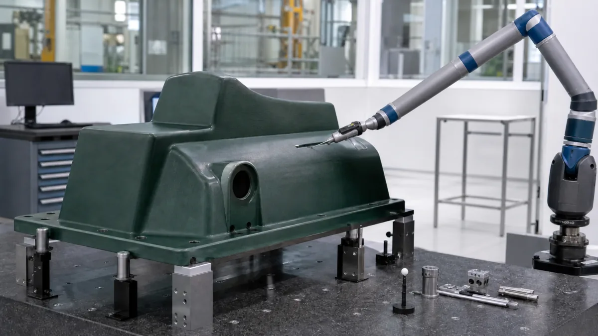
- Coordinate measuring machine (CMM) inspection for defined points and geometry
- 3D scanning compared with an approved CAD model
- Surface plates and indicators for flatness or local height checks
- Functional assembly gauges for fit, clearance, and fastener alignment
Each method has limits. A 3D scan can capture broad contour data efficiently, but its setup, alignment, filtering, and reporting method must be defined. A CMM can produce precise point data, but a flexible part may require support or controlled restraint. A functional gauge may best represent assembly performance, even when it does not report every geometric deviation.
For flexible or large parts, define whether inspection occurs:
- In a free-state condition
- Supported at specific points
- Clamped to datum fixtures
- Fastened to an assembly gauge
- After a stated conditioning period
The inspection method should match the functional condition. A cover that is installed with bolts around its perimeter should not necessarily be rejected based on unsupported free-state shape alone if it meets fit and appearance requirements when assembled.
Build a First-Article Inspection Plan
A first-article inspection plan converts the drawing into a practical verification process. It should be prepared before production parts are evaluated, not after questions arise.
The plan should identify each feature to be checked, its drawing reference, nominal value, tolerance or acceptance limit, datum scheme, measurement method, and result. It should also state whether the feature is functional, cosmetic, or informational.
A workable first-article plan typically includes:
- Document review: Confirm current drawing, CAD revision, material requirements, finish requirements, and approved deviations.
- Datum setup: Show how the part is oriented and supported for inspection.
- Critical dimensions: Measure fit-driving contours, interfaces, hole patterns, trim boundaries, and insert locations.
- General dimensions: Check overall envelope and noncritical features at an appropriate sampling level.
- Appearance review: Evaluate visible surfaces against the agreed zones and reference standard.
- Hardware and bonded features: Verify component identity, position, orientation, and applicable functional checks.
- Photographs or scan reports: Use these where they help document condition and feature locations.
- Disposition process: Record any variation, proposed corrective action, or approved concession before moving forward.
The first article should test the assumptions built into the tolerance scheme. If a critical feature is difficult to inspect, unstable in the fixture, or more restrictive than the assembly actually requires, revise the documentation before repeating that problem in production.
Common causes of first-article disagreement include missing datum definitions, conflicting CAD and drawing information, ambiguous free-state requirements, unsupported cosmetic expectations, and hole locations dimensioned from trim edges rather than assembly references.
Prepare a Better RFQ for Custom Molded FRP Parts
A useful RFQ gives the manufacturer enough information to review feasibility and identify questions before tooling decisions are made. Along with the part drawing and CAD model, provide:
- Assembly drawings or mating-part information
- Clearly identified critical-to-fit and critical-to-function features
- Datum scheme and GD&T where applicable
- Trim, cutout, and hole requirements
- Insert, bracket, and bonded-hardware details
- Material, finish, and environmental requirements
- Cosmetic zones and appearance references
- Inspection requirements and proposed first-article format
- Expected use condition, including loading or exposure details that affect design
For an overview of the early planning inputs, see what to know before starting a custom fiberglass product project. It can also help to review available custom composite product solutions when deciding how a molded part, secondary operations, and finishing requirements should be documented.
GFIND can review buyer drawings and application requirements for custom fiberglass and carbon-fiber components, including manufacturability, tooling, prototypes, molded production, finishing, and inspection to agreed references. When your tolerance package is ready for review, share the part requirements with GFIND to discuss the features that need the closest control.