FRP Inserts and Mounting Points: A Design Guide
Design durable FRP inserts and mounting points with practical guidance on load paths, reinforcement, corrosion, access, testing, and drawings.
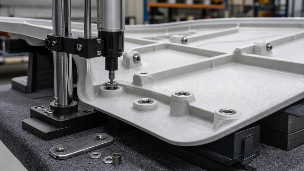
FRP inserts and mounting points should be designed as load-transfer features, not simply holes with hardware added later. A reliable connection starts by defining what attaches to the molded FRP part, the direction and frequency of loads, the required assembly process, and the environmental exposure.
For a custom molded part, the best insert strategy may be embedded hardware, a bonded insert, a post-installed threaded insert, a through-bolt with backing hardware, or a reinforced mounting pad. The right choice depends on the joint—not on the convenience of a single fastener style.
Identify Every Mechanical Interface
List every point where the FRP component connects to another part before finalizing the laminate, mold, or hardware schedule. This includes obvious mounting holes as well as less visible interfaces such as hinges, latches, cable clamps, lifting points, grounding provisions, service-panel fasteners, and brackets.
For each interface, define:
- The mating component: Frame, panel, bracket, enclosure, machine base, conduit support, or removable accessory.
- Fastener type and size: Bolt, screw, stud, rivet nut, threaded insert, clip, or through-bolt.
- Load direction: Tension, compression, shear, bending, torsion, vibration, or a combined load.
- Load condition: Static, repeated cycling, shock, transport, wind, operator force, or occasional service loading.
- Joint function: Permanent assembly, field replacement, periodic access, adjustment, sealing, or grounding.
- Assembly sequence: Which part is installed first, what tools are required, and whether a technician can reach both sides.
- Environmental exposure: Moisture, washdown, salt air, UV, chemicals, heat, freezing conditions, or electrically conductive dust.
A mounting point that only supports a light trim panel has very different needs than one carrying a cantilevered equipment bracket. Likewise, a hinge or latch can impose repeated local loads even when the attached door or cover is relatively light.
It is useful to create an interface schedule early in the design process. Assign each mounting feature an identifier that appears on the drawing, 3D model, and bill of materials. This avoids a common sourcing problem: a buyer specifies “pre-drilled mounting holes” but does not identify which holes require reinforcement, embedded hardware, sealing, or positional inspection.
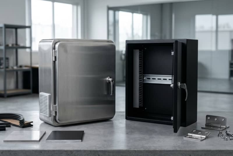
For assemblies such as equipment housings, the design should also consider how the FRP shell transfers loads into the supporting structure. Industrial equipment enclosure solutions may require distinct mounting strategies for wall attachment, base frames, internal equipment rails, access doors, and external accessories.
Choose Embedded, Bonded, or Post-Installed Hardware
Hardware should be selected based on the needed load, installation timing, access, serviceability, and risk of damaging the composite. “Insert” is a broad term; not every insert method is suitable for every FRP part.
| Approach | Best suited for | Key advantages | Important limitations |
|---|---|---|---|
| Embedded insert or stud | Known hardware location in a molded part | Hardware can be integrated during molding; no secondary drilling at that point | Position must be controlled before molding; replacement may be difficult |
| Bonded insert | Threaded attachment where backside access is unavailable | Can provide a threaded point in a finished part | Bond design, surface preparation, adhesive selection, and cure process must be defined |
| Post-installed threaded insert | Lower-load threaded attachment added after molding | Allows some flexibility in final hole placement | May be unsuitable for high pull-out, vibration, or thin laminate conditions |
| Through-bolt with washer or backing plate | High clamp load or accessible two-sided joint | Direct mechanical clamping and straightforward inspection | Requires access to both sides; local crushing and water entry must be managed |
| Reinforced pad with drilled hole | Bolted attachment without a dedicated insert | Simple, adaptable arrangement for certain joints | Hole finishing, sealing, edge distance, and backing hardware remain critical |
Embedded hardware
Embedded inserts, studs, nuts, or plates are generally considered when the mounting location is stable and repeatable from one part to the next. The insert must be retained and correctly positioned during molding. Its geometry should also allow the surrounding laminate and resin system to form a sound load-transfer region.
A metal insert surrounded by FRP should not be treated as if it were cast in a uniform metal block. Local forces move through the insert interface into the surrounding composite. The engineering question is whether the laminate, resin-rich zone, reinforcement package, and adjacent structure can carry those forces without cracking, delaminating, crushing, or loosening over time.
Bonded inserts
Bonded inserts can be practical when a threaded point is needed after molding or when the molded surface must remain smooth on the opposite side. However, their performance depends heavily on details that must be controlled, including hole preparation, surface cleanliness, adhesive compatibility, bond geometry, cure conditions, and prevention of insert rotation.
Do not specify a bonded insert solely by thread size. Define the insert material, design style, hole configuration, acceptable surface finish, adhesive or bonding process if required, and verification method. If the joint will see vibration, cyclic tension, heat, or significant leverage from an attached bracket, evaluate the complete insert-and-laminate system rather than the insert alone.
Post-installed hardware
Post-installed threaded inserts and similar hardware are often appropriate for light-duty covers, trim, cable routing components, and replaceable accessories. They can simplify late design changes, but they are not an automatic substitute for embedded reinforcement.
A post-installed insert may concentrate stress in a small region of laminate. If the part is thin, highly curved, lightly reinforced, or subjected to repeated loads, a locally reinforced mounting zone or a different joint method may be more appropriate.
Through-bolts and backing hardware
A through-bolt can be an effective and inspectable solution when both sides of the FRP are accessible. Use washers, load-spreading plates, or designed backing components where needed to reduce local bearing stress. The clamping arrangement should avoid crushing the FRP, especially in thin-wall parts or sandwich constructions.
Through-bolting is not necessarily simple if the backside is later enclosed, insulated, inaccessible, or exposed to moisture. Specify the hardware stack-up and assembly order, including sealants, washers, locknuts, spacers, and torque requirements where applicable.
Design Local Reinforcement Around the Load Path
FRP mounting-point strength is governed by the entire load path. The insert itself may be strong, but the surrounding laminate can still fail if the load is not spread into enough material.
Local reinforcement can include additional glass reinforcement, a thicker laminate zone, a molded pad, a backing plate, a core replacement area, or a shaped rib or flange that redirects force into the broader part geometry. The choice depends on whether the load is primarily tension, shear, compression, bending, or repeated cycling.
Consider these design questions:
- Does the attached component create leverage that turns a simple shear load into bending at the mounting point?
- Is the fastener clamping force likely to crush or indent the FRP surface?
- Does a concentrated load occur near a corner, cutout, flange transition, or curved surface?
- Will a bracket transmit vibration into the laminate?
- Is the feature located in a sandwich panel where a core may need local replacement or support?
- Can a rib, return flange, or larger mounting pad reduce stress more effectively than simply adding layers near a hole?
A local buildup should transition gradually into the base laminate where possible. Abrupt changes in thickness or stiffness can create stress concentrations. Reinforcement should also be oriented to support the actual force path. For example, a bracket that pulls outward from a wall may need a different reinforcement arrangement than a fastener loaded parallel to the surface.
Avoid relying on a thick cosmetic gel coat or surface resin layer as structural support. Fastener bearing, pull-through resistance, and insert retention should be provided by the structural composite design and any intended backing hardware—not by the finish layer.
Common mistakes include placing a mounting hole through a thin flange, attaching a stiff metal bracket to an unsupported flat panel, or increasing bolt diameter without increasing the surrounding load-bearing area. Larger hardware does not automatically make an FRP joint stronger.
Allow Access for Installation and Inspection
A well-designed mounting point must be buildable and serviceable in the real assembly. Confirm tool clearance, line of sight, hand access, fastening direction, and the ability to inspect the completed joint.
Questions to resolve before releasing the design include:
- Can the installer hold a nut, washer, or backing plate on the opposite side?
- Is there enough room for a socket, wrench, driver, torque tool, or drill fixture?
- Can a threaded insert be installed without damaging adjacent finished surfaces?
- Will a door, panel, internal component, or insulation block access after assembly?
- Can the joint be visually inspected for seating, sealant coverage, missing hardware, or damage?
- Can a failed insert, damaged fastener, or worn gasket be serviced without replacing the entire FRP part?
For enclosed components, access may need to be designed in rather than assumed. Removable panels, inspection openings, access pockets, captive hardware, or external mounting flanges can make assembly more repeatable. Each option introduces tradeoffs involving sealing, appearance, cost, and structural continuity.
If field replacement matters, document which hardware is replaceable and which is intended to remain integral to the molded component. An embedded stud can simplify assembly but may create a more involved repair if threads are damaged. A through-bolt may be easier to replace but may require two-sided access.
Manage Galvanic and Environmental Compatibility
FRP itself does not corrode like steel, but the hardware and interfaces around it can be affected by moisture, chemicals, temperature, and dissimilar-metal contact. Material selection should reflect the actual service environment.
Stainless steel, plated steel, aluminum, brass, and other metals each have different corrosion behavior. When dissimilar metals are used together in wet or salt-containing conditions, galvanic corrosion can become a concern. Carbon-fiber components require particular attention because carbon fibers can be electrically conductive and may contribute to galvanic interaction with certain metals when an electrolyte is present.
Evaluate the complete joint, including:
- Insert, bolt, washer, nut, backing plate, and bracket materials
- Coatings or plating on each hardware item
- Contact between metal and carbon-fiber or conductive materials
- Water traps around recessed fasteners or hardware pockets
- Sealants, adhesives, isolators, and gaskets
- Expected cleaners, chemicals, washdown agents, and temperature range
- UV exposure for exposed nonmetallic components and sealants
Electrical isolation may be needed between incompatible materials. Possible measures can include nonconductive washers, sleeves, coatings, sealants, isolating layers, or a revised hardware material choice. The selected method should not compromise clamp load, grounding requirements, fit, or inspection.
Do not assume that “stainless” alone solves corrosion concerns. Grade, finish, chloride exposure, crevice conditions, and contact with other materials all matter. If the assembly has electrical bonding or grounding requirements, those must be defined separately; an isolating joint may conflict with a required electrical path.
Control Hole Location and Edge Distance
Hole location is a functional tolerance, not just a cosmetic dimension. An accurately molded FRP part can still be difficult to assemble if mounting holes do not align with the frame, bracket, or mating panel.
The released design should establish:
- Hole diameter and shape
- Hole center location from stable datums
- Positional tolerance
- Surface profile or flatness requirements where hardware seats
- Counterbore, countersink, recess, or slot geometry
- Required edge finishing and sealing
- Which side receives the fastener head, washer, or nut
- Applicable hole pattern orientation
Edge distance must be evaluated in relation to fastener size, laminate thickness, load direction, reinforcement, geometry, and expected service loads. A hole too close to an edge can split, tear out, or distort the FRP under tension or shear. Curved edges, cutouts, corners, and flange transitions deserve particular scrutiny because their effective load path may be weaker than a flat, continuous panel.
Slots may help accommodate assembly variation or thermal movement, but they change how loads are transferred. If a slot is used, specify its orientation and explain whether the fastener is intended to clamp, slide, or locate the part. Include any required oversized washers, bushings, or load-spreading features.
Avoid dimensioning critical holes from trim edges that can vary. Whenever possible, establish functional datums that correspond to the mating assembly. For complex parts, a buyer may also define an inspection fixture, check gauge, or digital inspection reference.
Plan Pull Tests or Other Buyer-Defined Checks
Testing should reflect the actual failure risks of the connection. A generic pull test can be useful, but it does not prove every aspect of mounting-point performance.
Depending on the application, a buyer may define checks such as:
- Insert pull-out or pull-through testing
- Torque-to-rotate testing for threaded inserts
- Proof loading in tension, shear, or a combined direction
- Fastener torque verification
- Cyclic loading or vibration evaluation
- Visual inspection for cracks, voids, resin-starved areas, or delamination
- Hole location and pattern verification against agreed datums
- Fit checks using mating hardware, a fixture, or a representative bracket
- Environmental exposure testing when the service condition warrants it
The test method should identify the sample configuration, hardware stack-up, load direction, loading rate where relevant, acceptance criteria, number of samples, and the condition of the part before testing. An insert tested in a flat coupon may not represent an insert near a corner, rib, flange, core transition, or highly loaded bracket.
When specifying a pull test, clarify what is being evaluated. Possible failure modes include insert extraction, insert rotation, laminate pull-through, fastener failure, backing-plate deformation, local crushing, cracking, and bond failure. Acceptance should be based on the intended application and engineering requirements, not a generic number applied to unrelated part geometries.
Document Hardware in the Released Drawing
A released drawing should make the mounting-point design buildable without relying on assumptions. The hardware schedule, laminate requirements, hole details, and inspection references should agree with the 3D model and bill of materials.
At minimum, document:
- Hardware identification: Part number, material, finish, thread, and supplier-controlled specification where applicable.
- Mounting-point type: Embedded, bonded, post-installed, through-bolted, or reinforced drilled hole.
- Location and orientation: Datums, coordinates, positional tolerances, and clocking requirements.
- Local construction: Reinforcement area, laminate buildup, backing plate, core treatment, or molded pad requirements.
- Hole and feature geometry: Diameter, thread, depth, slot length, countersink, counterbore, and edge finishing.
- Assembly requirements: Hardware stack-up, sealant, isolator, adhesive, torque, locking method, or cure requirements when applicable.
- Inspection criteria: Required visual checks, dimensional references, fit checks, and buyer-defined test requirements.
- Environmental requirements: Corrosion-resistant material needs, isolation requirements, sealing expectations, and exposure conditions.
A clear note such as “install threaded insert” is usually insufficient. It leaves open questions about insert style, material, retention method, hole preparation, acceptable orientation, and verification. Conversely, avoid over-prescribing a process when performance is the real requirement. If an alternative hardware or molding approach is acceptable, state the functional requirement and require approval before substitution.
For a custom part RFQ, provide the latest drawing revision, 3D model when available, mating-part details, expected loads, hardware schedule, environment, and desired inspection plan. GFIND can review buyer drawings and application requirements as part of custom composite product support, including manufacturability, tooling, prototypes, molded production, finishing, and inspection to agreed references. Explore custom composite solutions or contact GFIND about a drawing review when you have a defined part concept or interface schedule.