FRP Tooling for Prototypes and Production Runs
Compare FRP tooling for prototypes and production runs, including patterns, molds, finish, repeatability, ownership, and first-article approval.
Choosing FRP tooling for prototypes and production begins with two questions: what must the finished part look and perform like, and how many consistent parts are required? A low-cost prototype tool may be appropriate for evaluating fit, while a repeat-production mold may need tighter dimensional control, a more durable surface, and a defined maintenance plan.
There is no universally “best” tooling route. The practical choice depends on part geometry, laminate process, cosmetic requirements, tolerances, production volume, and whether the tooling may be reused later. Buyers should define these inputs before comparing quotes so that a prototype mold is not mistakenly priced or used as a long-term production tool.
Start with Part Geometry and Production Volume
Part geometry and expected quantity should drive the tooling discussion before material selection. A simple, shallow panel with generous draft may be made from a relatively straightforward one-piece mold. A deep enclosure, textured cover, flanged housing, or multi-sided component may need split molds, removable inserts, or separate trim fixtures.
Begin by identifying:
- Part envelope: Overall length, width, depth, wall thickness, and weight targets.
- Surface classification: Cosmetic exterior, paint-ready surface, protected interior, or nonappearance surface.
- Geometry constraints: Deep draws, reverse features, sharp inside corners, undercuts, holes, ribs, and return flanges.
- Tolerances: Which dimensions are critical for assembly, sealing, mounting, or interchangeability.
- Production quantity: One evaluation piece, a small pilot run, periodic replacement parts, or ongoing repeat production.
- Manufacturing process: Open molding, vacuum-assisted methods, closed molding, compression molding, or another agreed process.
- Secondary operations: Trimming, drilling, machining, bonding, coating, inserts, or hardware installation.
Volume is not only a purchasing forecast. It affects how much effort makes sense for a durable mold face, reinforcement, alignment features, locating points, and repairability. A projected quantity should still be treated as an estimate unless a release schedule or purchase commitment has been defined.
For an overview of how design, tooling, molding, and finishing connect, see this guide to how custom fiberglass parts are made.
Separate Patterns, Molds, and Production Fixtures
“Tooling” can describe several different items. Treating them as one line item can create confusion about cost, ownership, and what is included in the part process.
Patterns create the mold shape
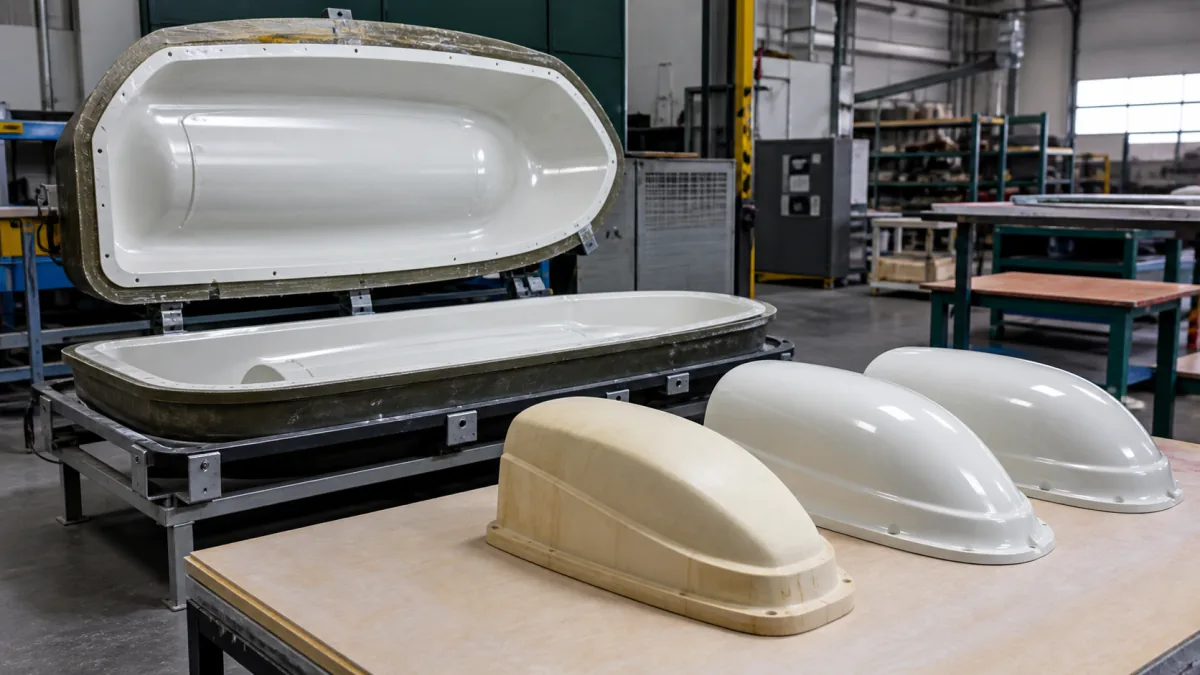
A pattern is the positive form used to create a mold. It may be CNC-machined, hand-built, 3D-printed, or assembled from another suitable material. Its surface quality strongly influences the mold and, ultimately, the molded part surface.
A pattern is often needed only during initial mold construction. It is not necessarily the item used for repeated part molding. Buyers should confirm whether the quoted tooling includes pattern design, pattern construction, sealing, surfacing, and any required revisions.
Molds create the parts
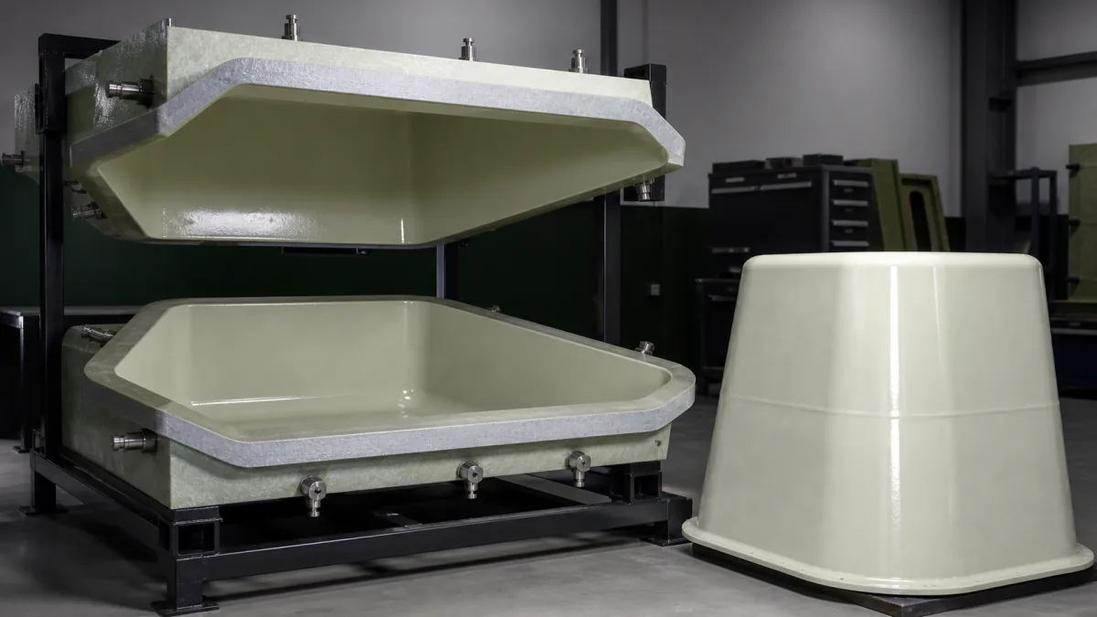
A mold is the negative cavity or forming surface that repeatedly produces the part. For a one-sided fiberglass part, the mold face commonly determines the visible surface. For a two-sided or closed-molded part, both tool surfaces may affect the finished geometry.
A mold may include:
- Mold flanges and a defined parting line
- Reinforcement structure or a support frame
- Alignment pins, bushings, clamps, or fastener locations
- Vacuum connections, vents, or seals when the selected process requires them
- Release-compatible mold surfaces
- A defined trim allowance
The mold should be described by its intended process and part surface—not just by a generic label such as “FRP mold.”
Fixtures support repeatable downstream work
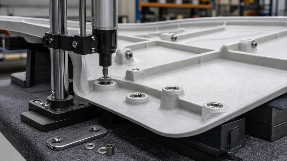
A production fixture does not always form the composite part. It may hold a molded shell during trimming, drilling, bonding, assembly, inspection, or shipment preparation.
Examples include:
- Trim and drill fixtures
- Bonding fixtures
- Assembly nests
- Inspection gauges
- Packaging supports for large or fragile parts
A part can be molded successfully but still vary after trimming or assembly if no suitable fixture controls those operations. When mounting holes, bonded components, or cutouts are critical, include those fixtures in the tooling scope.
Compare Prototype and Production Tooling Goals
Prototype and production tooling solve related but different problems. Prototype work focuses on learning: verifying form, fit, function, material behavior, and manufacturability. Production tooling focuses on making the agreed part repeatedly within defined requirements.
| Tooling consideration | Prototype-oriented approach | Production-oriented approach |
|---|---|---|
| Primary objective | Validate design and process assumptions | Support repeatable, controlled output |
| Expected quantity | One or a limited number of parts | Repeated runs over an agreed tool life |
| Design flexibility | Changes may be expected | Changes should be controlled and documented |
| Surface priority | May be adequate for evaluation only | Must meet specified cosmetic or functional expectations |
| Dimensional control | Focused on key fit dimensions | Defined across critical interfaces and repeat production |
| Support features | Basic handling may be sufficient | Often includes reinforcement, alignment, and process features |
| Commercial scope | Lower initial investment may be preferred | Lifecycle cost, maintenance, and ownership become more important |
A common mistake is to request a “production-quality prototype” without defining what production quality means. That phrase could refer to material construction, cosmetic finish, dimensions, tooling durability, or all of them. Instead, state the requirements individually.
For example, a functional prototype may need the intended laminate and mounting-hole locations but not a Class A exterior appearance. Conversely, a sales sample may need a representative gel-coated face but not a mold designed for extensive reuse.
Prototype tooling is also valuable for exposing design issues before larger tooling investment. It can reveal whether a feature traps the part in the mold, whether a flange creates an awkward trim operation, or whether a required tolerance is realistic for the selected composite process.
Match Tooling Material to Finish and Repeatability
Tooling materials should be selected based on the molding process, expected use, part size, surface expectations, and the likelihood of future revisions. The choice is not simply between “cheap” and “durable.”
Common options can include:
- Machined wood or board materials: Often useful for temporary patterns, design verification, or lower-demand applications. Surface sealing and stability matter.
- 3D-printed or additively made patterns: Useful when geometry changes quickly or when a complex pattern is needed for early-stage work. Layer lines, finishing, and thermal behavior should be considered.
- Composite tooling: Often selected for composite-part production because it can be shaped for the application and built with a finished mold face. Construction should match the intended process and service conditions.
- Metal tooling: May be appropriate where high repeatability, elevated temperatures, pressure, or a particular forming process justifies it. It can also bring different machining, handling, and cost considerations.
A smoother tool face can help achieve a smoother molded surface, but it does not guarantee the final appearance by itself. Resin system, gel coat or coating requirements, reinforcement print-through, laminate schedule, curing conditions, handling, and post-mold operations can all affect results.
Specify the visible surface in practical terms. Useful definitions may include:
- Side A versus Side B
- Molded finish, paint-ready finish, or textured finish
- Gloss level or texture reference, when applicable
- Permitted cosmetic variation
- Areas hidden after installation
- Whether sanding, filling, coating, or polishing is acceptable
Also separate surface appearance from dimensional repeatability. A tool with a high-quality cosmetic face may still require appropriate support, locating features, and inspection references to control critical dimensions through repeat production.
Plan Draft, Split Lines, and Demolding Access
A part must be released from its mold without damaging the part, tool, or finished surface. This basic requirement should influence the design early, not after the pattern is already complete.
Draft and undercuts
Draft is the taper that helps a part release from a mold. Required draft varies with geometry, texture, material system, and molding process. Smooth surfaces may release with less draft than textured or deep features, but the appropriate value should be reviewed for the actual part.
Undercuts prevent straight removal from a simple mold. They may require a split tool, removable insert, collapsible feature, secondary assembly, or a redesign of the feature. Do not assume a small undercut is insignificant; it can determine the entire tooling approach.
Split lines affect cost and appearance
A split line is where mold sections meet. It can create a seam, flash, or trim requirement on the part. Place it where it is functional, manageable during molding, and acceptable for the finished product.
When reviewing split lines, confirm:
- Which surfaces remain uninterrupted and cosmetic
- Where flash or witness lines may appear
- Whether the seam will be trimmed, sanded, or concealed
- How mold sections align
- Whether hardware, flanges, or access features interfere with separation
Allow room for hands, materials, and removal
CAD geometry can appear moldable while remaining impractical for technicians to laminate, place reinforcements, close a tool, or remove a finished part. Tooling reviews should consider access for materials, compaction, vacuum consumables if used, lifting, trimming, and safe part removal.
This is why a manufacturability review before tool release is valuable. GFIND can review buyer drawings and application requirements as part of support for custom composite projects, helping identify tooling and molding considerations before production decisions are finalized.
Define Ownership, Storage, and Tool Maintenance
Tooling is a physical asset with commercial and operational responsibilities. Resolve those responsibilities in writing before a supplier begins construction.
At minimum, confirm:
- Ownership: Who owns the pattern, mold, fixture, CAD-derived tool files, and any inserts after payment?
- Tool location: Where will each item be stored, and can it be transferred if needed?
- Storage conditions: How will tools be protected from moisture, contamination, distortion, impact, and ultraviolet exposure where relevant?
- Maintenance scope: Who is responsible for cleaning, polishing, resealing, minor repair, or replacement of consumable items?
- Tool-life definition: What constitutes normal wear, damage, or end of intended service life?
- Change control: How will engineering changes be requested, priced, approved, and recorded?
- Access and disposition: What happens to the tool if production pauses or the program ends?
Avoid vague statements such as “tooling included.” The purchase order or tooling agreement should identify the specific assets, the intended use, and the handling of future modifications. If a tool is expected to serve multiple manufacturing lots, clarify whether inspection, refurbishment, or requalification is needed before a later run.
Use a First Article Before Repeat Production
A first article is the practical checkpoint between tool completion and repeat manufacturing. It allows the buyer and manufacturer to compare an actual part with the agreed drawing, model, approved sample, or inspection references.
First-article approval should be more than a visual acknowledgment that a part exists. Define what will be reviewed, how it will be measured, and what approval permits.
A useful first-article plan may cover:
- Part revision level and material or laminate requirements
- Critical dimensions and measurement method
- Hole, cutout, and insert locations
- Surface appearance by defined area
- Weight, thickness, stiffness, or other functional requirements when applicable
- Trim boundaries and edge condition
- Fit with mating components, if assemblies are available
- Required photos, inspection records, or retained samples
- Disposition of deviations and changes before repeat production
Not every dimension requires the same level of inspection. Identify the dimensions that control installation, sealing, structural interfaces, or interchangeability. For cosmetic products, provide an approved appearance sample or a clear standard rather than relying on subjective descriptions such as “good finish.”
If revisions are needed after the first article, document whether the change affects the tool, the process, the trim fixture, or only the part work instructions. That distinction prevents a tooling modification from being overlooked as a minor production adjustment.
Ask the Right Tooling Questions in an RFQ
A well-prepared RFQ makes it easier to receive quotes that are comparable and technically relevant. Send the latest drawing or 3D model, but also provide the application details that geometry alone cannot show.
Include the following information where available:
- Part number, revision, and quantities by release or year
- 3D model, 2D drawing, and critical dimensions
- Intended use environment and performance needs
- Material, reinforcement, resin, core, and flame or environmental requirements, if specified
- Desired molding process, or openness to a supplier recommendation
- Cosmetic surface requirements and reference samples
- Required color, coating, texture, or finish operations
- Mating parts and assembly interfaces
- Required holes, inserts, bonded features, and secondary operations
- Inspection requirements and acceptance criteria
- Prototype quantity and planned repeat-production quantity
- Requested tooling ownership, storage, and maintenance terms
- Packaging, handling, and shipment requirements
Ask suppliers to distinguish the quoted cost and scope for patterns, molds, trim fixtures, inspection fixtures, first articles, and production parts. Also ask what assumptions the quote makes about expected tool use, finish level, part geometry, and revision stability.
For projects with several possible manufacturing routes, review available custom composite solutions before locking the RFQ into a tool concept that may not suit the application.
The best FRP tooling for prototypes and production is the one that matches the actual part requirements and commercial plan—not the most elaborate tool by default. Define the part’s geometry, quantity, finish, critical features, and approval method first, then select tooling that supports those priorities.
If you are preparing a custom composite RFQ, GFIND can review drawings and application requirements for manufacturability, tooling, prototypes, molded production, finishing, inspection to agreed references, and shipment preparation. Contact GFIND about a composite tooling project when you have the design inputs ready.