Molded FRP Draft Angle Design and Parting Lines
Learn how to set draft angles, locate parting lines, manage undercuts, and document trim and inspection requirements before FRP tooling release.
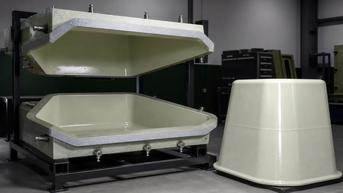
Draft angles and parting lines determine whether a molded FRP part can release from its tool without damaging the laminate, gel coat, mold surface, or critical edges. They should be resolved before tooling release—not treated as minor drawing details after the part shape is complete.
For molded FRP draft angle design, first establish how the tool opens and where the part must move during release. Then apply enough draft for the selected process, surface finish, depth, texture, and tolerance needs. A good design also makes trim, inspection, and cosmetic acceptance clear to the toolmaker and production team.
Start with the Tool Opening and Demolding Direction
Choose the primary demolding direction before assigning draft or placing a parting line. In simple terms, every surface that contacts the mold needs to release in a direction that does not cause the part to lock onto the tool.
A useful early exercise is to review the CAD model along the proposed pull direction:
- Identify surfaces that are parallel to the pull direction.
- Mark surfaces that taper inward and will create a mechanical lock.
- Check pockets, returns, louvers, brackets, and openings for trapped geometry.
- Determine whether the part can release from one mold half or needs a split tool, insert, slide, collapsible feature, or secondary operation.
- Confirm whether the part remains on the intended tool half after opening.
The preferred pull direction is usually the one that minimizes tool complexity while protecting functional and visible surfaces. It is not always perpendicular to the largest face of the part. A housing, cover, panel, or enclosure may need a pull direction selected around its deepest wall, most important sealing face, or most visible exterior surface.
For an open-mold FRP part, the mold face typically defines the cosmetic side. The opposite side may have more freedom for laminate buildup, attachments, and secondary finishing, but it still must be reachable and releasable. For matched-mold, resin transfer molding, compression molding, or other closed-mold approaches, both tool halves and the cavity interface require careful release planning.
Do not assume a nominal CAD “vertical” direction is the actual demolding direction. Include a pull-direction indicator on the drawing or a dedicated DFM view. This prevents a part designer, toolmaker, and buyer from evaluating the same model from different assumptions.
Set Draft from Geometry, Process, and Finish Needs
There is no universal molded FRP draft angle. Draft should be selected from the part geometry, molding process, tool material and finish, release system, surface texture, depth of draw, and required appearance.
More draft generally supports easier release, while deeper walls, textured surfaces, tight internal features, and surfaces likely to grip the mold may need additional relief. Shallow, smooth features can sometimes use less, but low or zero draft raises release risk and should be specifically reviewed with the manufacturer. The agreed value should come from a manufacturer DFM review of the actual geometry and molding process.
| Feature condition | Draft-angle design consideration |
|---|---|
| Smooth, shallow exterior wall | Modest draft may be workable if the surface and tool finish support release. |
| Deep box wall or tall return | Use more draft because contact area and release friction increase with depth. |
| Textured or grained cosmetic surface | Increase draft to avoid scuffing, drag marks, or texture damage during release. |
| Internal pocket or recess | Check draft particularly carefully because internal walls can lock onto a core or insert. |
| Gel-coated visible surface | Protect the appearance requirement; inadequate draft can cause cosmetic damage at release. |
| Tight mating or sealing feature | Balance functional geometry with release needs; consider a separate insert or secondary-machined datum. |
| Compression- or matched-mold feature | Review draft with the complete cavity, flow, venting, and tool-opening approach. |
Draft is measured from the demolding direction, not from an arbitrary global axis. A stated draft value may provide little or no release benefit if it is not oriented correctly relative to the tool-opening direction.
Avoid relying on zero draft
Zero-draft walls are often assumed to be acceptable because composite materials can have some flexibility. That assumption can lead to inconsistent release force, gel-coat marking, edge cracking, mold wear, and part-to-part variation. Flexing a part to remove it may also compromise dimensional stability or cause problems at bonded or embedded features.
If a functional surface truly must have zero draft, document it as an intentional exception. The DFM review should then address:
- Which tool element forms the feature
- How the feature releases
- Whether it needs a removable insert or separate mold section
- Whether the surface will be machined after molding
- Which dimensions are measured before and after finishing
- What appearance limitations are acceptable
The practical question is not “What is the minimum draft angle?” It is “What draft provides repeatable release while preserving the required function and finish?”
Place Parting Lines Around Function and Appearance
A parting line is where mold sections meet. It affects tool construction, flash control, finishing work, visual appearance, and dimensional references. Place it deliberately rather than allowing it to fall wherever the CAD split is easiest.
Good parting-line locations commonly follow a natural edge, flange, corner radius, beltline, or other change in geometry. These locations can hide a small witness line, provide a practical trim boundary, and avoid putting the mold split across a broad show surface.
When reviewing parting-line options, consider four priorities:
- Release: The split must let all molded surfaces pull free.
- Appearance: Keep witness lines, flash, and possible finishing marks away from customer-facing or highly visible zones.
- Function: Avoid sealing lands, precision mating faces, snap locations, adhesive bond paths, and critical locating features where possible.
- Access: Ensure the mold can be closed, clamped, vented, cleaned, and maintained, and that the part can be trimmed after molding.
A parting line across a visible panel may be technically moldable but commercially undesirable. If it cannot be moved, define the permitted appearance condition. For example, the drawing or quality documentation can identify the area as a cosmetic zone, state whether a witness line is allowed, and establish the agreed viewing distance, lighting condition, and allowable finishing method.
Do not confuse a parting line with a trim line
A parting line is a tooling interface. A trim line is where excess material is removed to achieve the finished edge. They may be near each other, but they do not have to coincide.
Separating the two can be beneficial. A tooling flange may be needed outside the finished edge for mold closure, resin control, vacuum sealing, handling, or clamping. The finished part is then cut back to a specified trim boundary. This arrangement can improve process control, but only if edge access and tolerances are clearly defined.
Eliminate or Deliberately Plan Undercuts
An undercut is any feature that prevents straight-line removal in the chosen demolding direction. Common examples include reverse tapers, inward-facing lips, hook forms, captured channels, side holes, deep return flanges, and recessed pockets behind an edge.
The most economical approach is usually to redesign the feature so it releases with the main tool opening. Options may include:
- Reorienting the feature to align with the pull direction
- Replacing a reverse lip with a separate attached component
- Opening a continuous pocket to an edge
- Breaking one complex molded component into two simpler parts
- Using a post-machined hole or slot instead of molding it
- Changing a sharp return into a more open, drafted form
Sometimes an undercut is necessary. In that case, it should be a conscious tooling decision rather than an overlooked CAD detail. Possible solutions include removable inserts, side actions, collapsible tooling elements, flexible tool components, or post-molding assembly. Each option has implications for tooling cost, maintenance, dimensional control, cycle steps, and inspection.
A feature can also behave like an undercut because of laminate spring-back or part flexibility, even if the nominal CAD geometry appears releasable. This is especially relevant for long channels, deep shells, tightly radiused returns, and parts with uneven reinforcement. Review the part’s likely release behavior, not just the mathematical draft analysis.
Coordinate Trim Flanges, Cut Lines, and Edge Access
FRP parts frequently require trimming after molding. The design should therefore define the finished boundary, the allowed edge condition, and the space needed to access the cut line with the intended method.
A trim flange can provide sacrificial material outside the finished part profile. It may support molding and handling while giving the trimming operation a stable, accessible path. However, an oversized or poorly located flange can increase material use, create difficult access, or leave a challenging edge to finish.
Specify the following before tool release:
- The finished trim line or 3D trim curve
- Whether dimensions reference the molded condition or finished trim condition
- The trim tolerance and measurement method
- Required edge radius, chamfer, deburr level, or seal treatment
- Areas where fiber exposure is unacceptable
- Whether the edge is cosmetic, structural, bonded, sealed, or hidden
- Hole, slot, and cutout locations relative to stable datums
- Clearance for routers, saws, waterjet cutting, CNC trimming, or manual finishing, as applicable
Avoid placing a trim line deep inside a narrow channel or immediately behind a return where tools cannot reach it cleanly. Likewise, do not put a tight positional tolerance on a hand-finished edge without discussing the intended trim process and datum scheme.
Where a part joins another component, distinguish between the molded perimeter, trimmed perimeter, and functional interface. These can differ due to laminate edge finishing, gasket compression, bonding overlap, or assembly clearance.
Review Inserts, Ribs, Returns, and Deep Features
Features that look minor in CAD can dominate mold complexity. Review them individually during the DFM review.
Inserts and embedded hardware
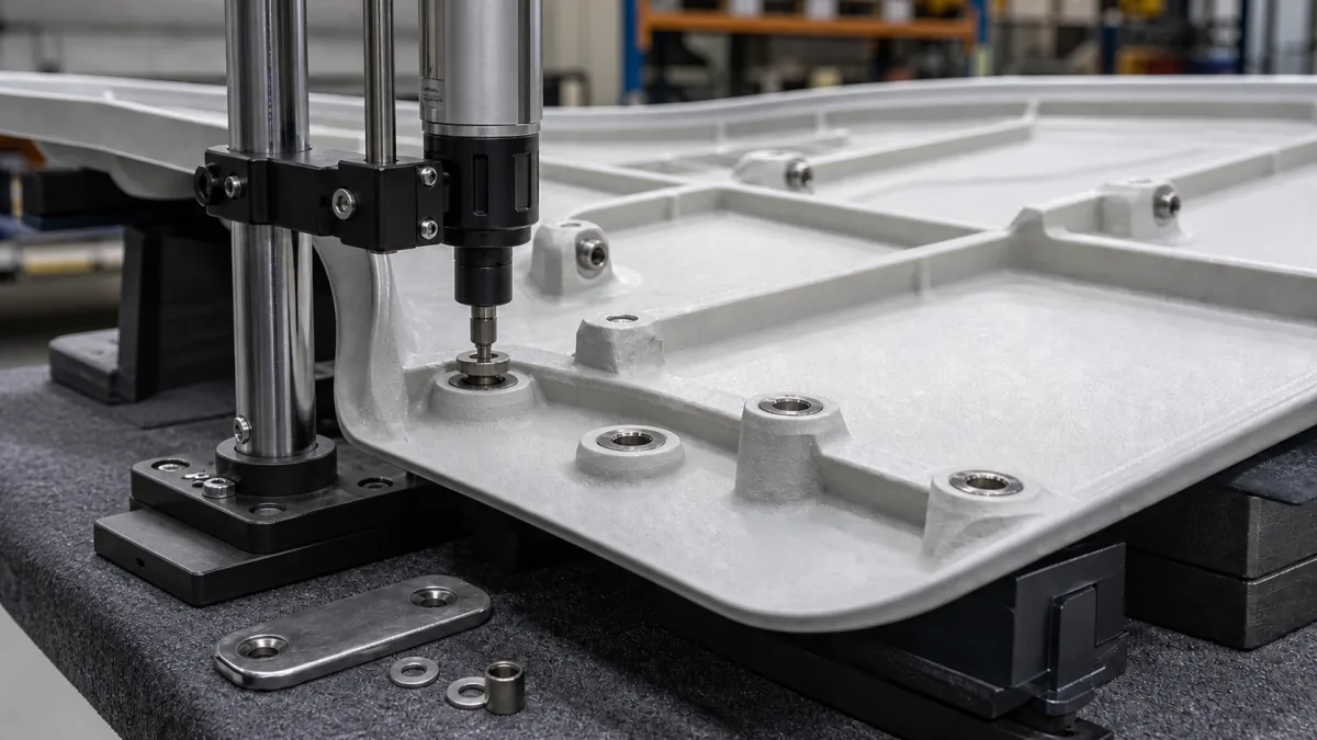
Threaded inserts, plates, studs, bushings, and other embedded components need a defined installation approach. Confirm whether they are molded in, bonded in afterward, mechanically fastened, or installed after a machining step.
For molded-in inserts, evaluate their ability to remain correctly located during molding and release. Also confirm protection of threads, accessibility of the tool around the insert, isolation requirements, and the inspection reference for position. If an insert creates a local undercut or blocks tool access, a post-mold installation may be the more practical option.
Ribs and stiffeners
Ribs can improve stiffness, but tall thin ribs, sharp intersections, and narrow channels may be difficult to laminate consistently or release cleanly. Provide draft on rib walls, use reasonable radii at their bases, and confirm there is physical access for reinforcement placement and compaction where the selected process requires it.
Do not assume a rib can be dimensionally controlled like an injection-molded plastic feature. Composite thickness, resin distribution, reinforcement architecture, and secondary trimming can affect the resulting feature. Identify which rib dimensions are function-critical and which are reference-only.
Returns, hems, and deep channels
Returns and wraps create visual refinement and can stiffen an edge, but they frequently introduce restricted access and release challenges. Review:
- Draft on both the inner and outer walls
- Corner radii large enough for reinforcement to conform
- Access for molding, consolidation, and trimming
- Risk of bridging at sharp inside corners
- Whether the return should be molded, bonded as a separate detail, or formed through a different tool arrangement
Deep recessed features deserve special attention because the lateral clearance produced by draft changes with feature depth. A given draft can create a meaningful opening at the mouth of a deep cavity, while insufficient draft can make the part grip the mold across a large contact area.
Complete a DFM Review Before Tooling Release
A structured DFM review is the best time to resolve draft, parting, trim, and tooling assumptions. Once the tool is built, changes can be more disruptive than correcting the CAD model early.
At minimum, provide the latest native CAD file or neutral 3D format, a controlled drawing, and a written list of requirements. If revisions are possible, identify the current revision clearly and avoid releasing tooling from an uncontrolled reference model.
Use this checklist during the review:
- Confirm the primary demolding direction.
- Run a draft analysis using that direction.
- Identify all zero-draft surfaces and approve or revise them.
- Mark the intended parting line and any separate tool inserts.
- List all undercuts and the proposed resolution.
- Define cosmetic surfaces and locations where witness lines are unacceptable.
- Identify trim curves, finished edges, cutouts, and machining access.
- Establish functional datums and distinguish them from noncritical molded surfaces.
- Define key dimensions, tolerances, and the inspection approach.
- Review inserts, ribs, returns, deep draws, and tight inside radii.
- Clarify the intended molding process and finish system.
- Record open questions before authorizing tool construction.
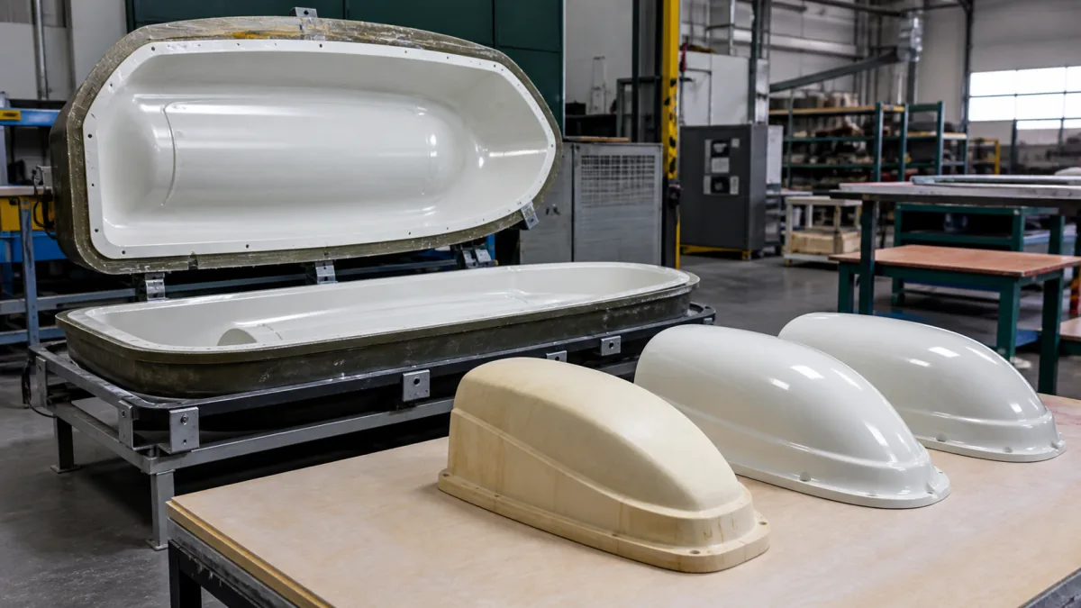
For projects moving from concept to production, the relationship between the tool, prototype parts, and production method should also be considered. This guide to FRP tooling for prototypes and production can help teams decide which geometry needs early validation and which details require a production-representative tool.
Record Approved Geometry and First-Article Checks
The final tool should be based on an approved record of geometry, not informal email markups or a model with unclear revision status. The release package should state what constitutes the controlled part definition and how disagreements are resolved.
A practical package may include:
- Revision-controlled CAD and 2D drawings
- Demolding direction and draft-analysis views
- Parting-line and trim-boundary definitions
- Cosmetic-zone map and finish expectations
- Datum structure and critical dimensions
- Hole, insert, and cutout requirements
- Material or laminate requirements when applicable
- Inspection points, measurement references, and acceptance criteria
- Approved deviations or tooling-specific assumptions
First-article inspection should check more than overall length, width, and height. It should verify the conditions most likely to be affected by the mold split and release strategy: trim edges, flange flatness, insert positions, hole locations, mating features, visible witness lines, surface condition, and access for downstream assembly.
Where fit with another component matters, use the actual mating part, a validated fixture, or an agreed interface gauge whenever practical. A part can meet isolated dimensions yet still fail to assemble if the datum scheme does not represent how it is used.
Before requesting quotes, organize models, drawings, quantities, finish requirements, inspection needs, and open technical questions. This custom FRP RFQ preparation guide outlines the information that helps suppliers review a composite part accurately.
GFIND can review buyer drawings and application requirements for manufacturability, tooling, prototypes, molded production, finishing, and inspection references. For a project-specific discussion, share the controlled geometry and requirements through the GFIND contact page.