Low-Volume Automotive Body Panel Sourcing Guide for OEMs
Plan low-volume automotive body panels with clear master data, tooling, fit, finish, approvals, packaging, and replacement-part controls for repeatable builds.
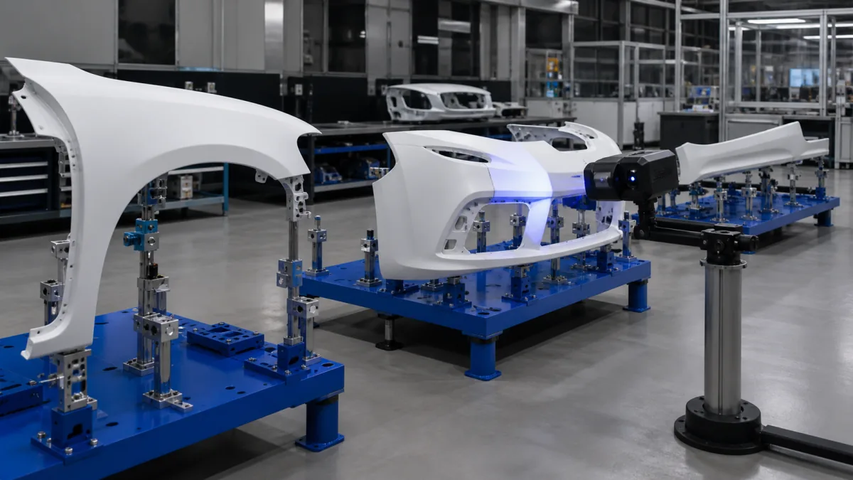
Low-volume automotive body panel sourcing succeeds when the buyer defines more than the visible shape. A supplier needs controlled surface data, mating conditions, mounting strategy, finish expectations, inspection references, and a realistic plan for prototype and repeat production. Without those inputs, a panel may look correct by itself but fit poorly on the vehicle or create avoidable paint and assembly work.
For specialty vehicles, restomods, motorsports applications, limited-run commercial equipment, and other small programs, the RFQ should function as a build specification—not just a request to quote a CAD file. The following framework helps engineering and purchasing teams source custom FRP body panels with fewer assumptions.
For an overview of common composite exterior part types, see automotive body panel solutions.
Define the Vehicle Program and Production Volume
Start by describing the program that the panel must support. “Low volume” has no single tooling or quality definition. A one-off prototype, a pilot build, and a service-part program can require very different manufacturing approaches even when the exterior geometry is identical.
State the intended use of each part:
- Styling model, show vehicle, prototype, or test mule
- Track-only, off-road, commercial, or on-road vehicle application
- Pilot build, limited production run, or replacement part
- Painted exterior skin, textured molded surface, or concealed component
- Standalone panel, bonded assembly, or bolted serviceable part
Then provide expected quantities by phase. Separate prototype quantities from annual or total repeat quantities. This helps determine whether the initial tool should prioritize speed, low initial cost, surface quality, dimensional control, durability, or a balance of those factors.
A useful RFQ volume statement might look like this:
| Program phase | Quantity to state | Why it matters |
|---|---|---|
| Design-validation prototypes | Number of pieces and iterations | Determines how much change tolerance is needed |
| Pilot or pre-production build | Expected build quantity | Affects tool and inspection planning |
| Repeat production | Annual and total anticipated quantity | Helps evaluate tooling durability and process consistency |
| Service parts | Expected years of availability and batch size | Influences storage, revision, and replacement-part planning |
Also identify vehicle-side dependencies. A front fascia, for example, may need to work around lamps, grille inserts, ducts, sensors, impact structures, undertrays, and existing fastening points. Review the intended assembly early when sourcing an FRP vehicle front fascia, because these interfaces often drive more risk than the exterior surface itself.
Establish Master Surfaces and Mating Data
The supplier should know which data set governs the part. A visual render, scanned body shell, legacy fiberglass part, and production CAD model are not interchangeable references.
Provide a controlled package that identifies:
- The current CAD revision and file format
- The master exterior surface or styling surface
- Nominal section thickness, where applicable
- Trim lines, shut lines, and edge-return requirements
- Vehicle-side mating surfaces and surrounding components
- Datums, coordinate system, and measurement references
- Any scan data, its alignment method, and known limitations
- Sections or drawings that clarify areas not fully defined in CAD
For a panel that mates to existing sheet metal, plastic, glass, lamps, or trim, provide those adjacent surfaces—not only the new panel. The part cannot be designed reliably around a gap if the other side of the gap is absent from the data package.
When physical vehicle data is the governing reference, specify it clearly. For example, a buyer may state that a supplied buck, scan, or vehicle shell is the fit master for a prototype phase. That is different from requiring exact conformity to nominal CAD. If scan data and CAD disagree, identify which one takes precedence in each region.
Clarify Class-A Expectations
“Class A” is often used loosely in automotive sourcing. It should not be treated as a universal acceptance criterion. In practical terms, it usually refers to an exterior surface intended to achieve a high visual standard after the agreed finishing and paint process.
For composite panels, surface outcome depends on the molding process, tool surface, material system, part geometry, reinforcement layout, post-mold preparation, primer, paint system, and inspection conditions. Buyers should define the required appearance rather than rely on the label alone.
Confirm:
- Which surfaces are customer-visible after assembly
- Whether the part will be painted, wrapped, coated, or left exposed
- The required paint-ready condition at handoff
- Whether print-through, pinholes, read-through, sink, or fiber texture are acceptable in any zone
- Inspection lighting, viewing distance, and comparison method
- Whether minor finishing by the buyer or paint shop is expected
Do not specify a “Class-A panel” while supplying only an incomplete exterior skin and no finish standard. That leaves a critical quality threshold open to interpretation.
Set Gap Flush and Mounting Expectations
A panel’s fit is an assembly requirement. Gaps and flushness depend on the panel, its mounting features, the vehicle body, adjacent parts, fastening sequence, and adjustment range.
Define target gaps and flushness by location when appearance matters. Include tolerances or acceptable ranges, along with the vehicle condition used for evaluation. A hood-to-fender gap measured on a supported body-in-white may not match the same gap on a fully assembled vehicle with seals, lamps, and bumper hardware installed.
For each interface, identify:
- Adjacent component and its revision
- Target gap and allowable variation
- Flushness target and direction of allowable offset
- Measurement datum and measurement location
- Assembly sequence and fastening order
- Required adjustability in slots, brackets, or shims
- Whether seals, weatherstrips, lamps, grilles, or trim are installed during fit check
Avoid assuming that adhesive alone will correct panel variation or body-side variation. Bonding can be appropriate, but it reduces post-installation adjustability and requires clear instructions for locating, clamping, cure, and surface preparation.
Mounting points should be designed for the actual load path. A thin composite flange may not be sufficient for repeated fastener installation, vibration, latch loads, or an unsupported cantilever. Areas around fasteners and hinges may need local reinforcement, inserts, backing plates, or separate brackets.
Choose Tooling for Prototype or Repeat Runs
Tooling selection should follow the program objective. The least expensive initial tool is not always the lowest-cost choice if the program needs multiple prototype loops, a paint-sensitive exterior surface, or repeatable service parts.
| Tooling approach | Best suited to | Main advantage | Main limitation to assess |
|---|---|---|---|
| Development or prototype tool | Early fit and styling validation | Lower commitment while design is changing | May not be appropriate for extensive repeat use or final surface targets |
| Production-oriented composite tool | Limited runs requiring repeatability | Can support a more stable molded process | Requires more defined data before release |
| Machined tool | Controlled geometry and higher surface demands | Strong dimensional and surface reference potential | Higher upfront investment and longer design commitment |
| Existing-part or scan-derived tool | Legacy restoration or adaptation work | Useful when native CAD is unavailable | Accuracy depends on the source part and scan alignment |
The right approach depends on the part’s size, geometry, draw direction, undercuts, flange access, target finish, material construction, and planned quantity. Tooling conversations should include trim fixtures, drill fixtures, checking fixtures, and assembly bucks where needed. A good mold alone does not guarantee that every trimmed, drilled panel will fit the vehicle consistently.
Ask what tool revisions are included in the plan and what triggers a new tool, insert, or rework. Design changes after tool release are common in low-volume programs, especially around lamps, brackets, ducts, and mounting tabs. Establish a formal approval point before releasing production-oriented tooling.
Plan Reinforcement Brackets and Hardware
Composite body panels need a complete mounting concept. The exterior shell may be only one element of the finished assembly.
Document every non-cosmetic item that must be included or accommodated:
- Metal reinforcement brackets and their material requirements
- Bonded or molded-in inserts
- Threaded hardware, rivet nuts, clips, and retainers
- Latches, hinges, struts, and tether points
- Lamp brackets, grille mounts, duct attachments, and sensor provisions
- Seals, edge trim, isolators, and anti-rattle materials
- Drainage, access holes, and service clearances
State whether hardware is buyer-supplied, supplier-sourced to a specified part number, or excluded from the part. If hardware is to be installed, define its orientation, torque-sensitive conditions, corrosion-isolation requirements, and inspection criteria.
Be careful with dissimilar materials. Metal brackets, fasteners, carbon fiber, fiberglass, and adjacent aluminum or steel structures can require isolation or coating decisions based on the vehicle environment and design requirements. The correct solution depends on the materials, fastening method, moisture exposure, and electrical requirements; it should be reviewed by the responsible engineering team.
Agree Surface Preparation and Paint Handoff
A molded composite panel is not automatically ready for paint. The handoff condition must be explicit because “paint-ready” can mean anything from basic mold release removal to a primed panel that has passed a defined appearance review.
Set the handoff level in writing:
- As molded: Part is supplied in its molded state, with normal post-mold operations defined separately.
- Trimmed and prepared: Edges, holes, and agreed surface preparation are completed, but final paint-shop work remains.
- Primer-ready or primed: The supplier and buyer agree on the primer system, preparation scope, and inspection reference.
- Painted finish: Color, gloss, texture, masking, color match process, and acceptance conditions must all be documented.
Discuss the full paint process with the party responsible for final coating. Cure temperatures, solvent exposure, sanding procedures, and coating-system compatibility can affect panel construction and appearance. Do not assume a material or primer is compatible with every paint system.
Specify which side requires finish work. The inside of a hood, fascia, or access panel may need an agreed cosmetic standard, edge treatment, or texture even if it is not painted. Conversely, hidden surfaces may only need functional coverage. Separating these zones can avoid unnecessary cost while protecting visible quality.
Use Trial Fit and First-Article Approval
Trial fit is one of the most valuable controls in low-volume automotive body panel sourcing. It verifies the actual relationship between the molded panel and the intended vehicle assembly before a full repeat batch is authorized.
A practical first-article process typically includes:
- Molded, trimmed, and drilled part identified by revision
- Fit check on the agreed vehicle, buck, or checking fixture
- Installation of relevant adjacent parts and hardware
- Gap, flushness, hole-position, and interference review
- Photographs of agreed inspection areas
- Record of deviations, rework actions, and accepted concessions
- Written approval criteria for moving into the next build stage
Define whether first-article approval is visual only, dimensional only, installed-vehicle fit, or all three. If a checking fixture is used, establish whether it is a manufacturing aid or the formal acceptance reference.
Do not approve a part based only on an uninstalled tabletop inspection when the program’s primary risk is vehicle integration. Likewise, do not rely solely on vehicle fit if the part also has paint-sensitive outer surfaces that require a defined appearance review.
Control Revisions, Packing, and Replacement Parts
Low-volume programs often face revision drift: one batch is built to an early CAD file, a bracket changes later, and replacement parts no longer match the assembly. Prevent this by treating revision control as part of the sourcing requirement.
Every part should be traceable to its approved configuration. Agree on:
- Part number, revision level, and visible or packaged identification
- Approved CAD, drawing, and bill-of-material references
- Change-request and approval process
- Treatment of existing inventory after a revision change
- Interchangeability requirements between revisions
- Records retained with first-article and inspection results
Packing also deserves engineering attention. Large FRP panels can be vulnerable to edge damage, flange distortion, point loading, abrasion, and movement during transport. Define the packing condition needed for the part: protective film where appropriate, edge protection, separators, support locations, orientation, and whether reusable racks are required.
For replacement parts, specify whether they must fit vehicles built to earlier revisions. Service parts may need different labels, hardware kits, installation notes, or protective packaging than line-build parts. A replacement part that arrives without its unique bracket, clip, or mounting instruction may not be usable even if the molded shell is correct.
Common Sourcing Mistakes to Avoid
The most preventable issues usually come from missing interfaces and undefined acceptance criteria. Watch for these common gaps:
- Quoting from exterior CAD without adjacent vehicle data
- Calling for Class-A quality without defining paint handoff or visual acceptance
- Releasing tooling before mounts, lamps, grilles, and seals are finalized
- Specifying gaps without identifying the measurement condition
- Treating trim, drilling, and hardware installation as assumed operations
- Approving a prototype without a documented revision and deviation record
- Ordering repeat parts without confirming configuration control and packing requirements
For additional planning considerations before requesting custom exterior components, review what OEM buyers should know before starting a custom automotive exterior parts project.
Build a More Complete RFQ
A strong RFQ for low-volume automotive body panels includes current master data, adjacent interfaces, quantities by phase, material and finish intent, tooling expectations, mounting details, fit criteria, first-article requirements, revision control, and packing needs.
GFIND can review buyer drawings and application requirements for manufacturability, tooling, prototypes, molded production, finishing, inspection to agreed references, and shipment preparation. Before requesting a quote, organize the inputs above so suppliers can identify assumptions early and propose a manufacturing path that matches the actual vehicle program.