Modular FRP Booth Planning for Repeat Deployment
Plan modular FRP booths for repeat deployment with practical guidance on modules, transport, utilities, finishes, installation, and revision control.
Modular FRP booth planning works best when the booth is treated as a repeatable system rather than a one-off enclosure. Define the use case, establish module and shipping limits, standardize connection points, and freeze controlled interfaces before the first unit is produced. That approach makes later deployments easier to quote, transport, install, service, and update.
A modular fiberglass-reinforced-plastic (FRP) booth can serve as a guard station, gatehouse, attendant booth, payment booth, inspection station, equipment enclosure, or service kiosk. The right configuration depends less on the label and more on who uses it, where it sits, what it connects to, and how frequently it must move or be reproduced.
Define the Booth Use and Occupancy Needs
Start with the operating task. A booth intended for a single seated gate attendant has different spatial, glazing, HVAC, counter, and electrical needs than a two-person security booth with monitoring equipment or a drive-up service booth.
Document these inputs before selecting wall thicknesses, windows, or module breaks:
- Occupants: Normal and maximum number of people inside at one time.
- Work position: Seated, standing, alternating, or accessible counter-height requirements.
- Duty cycle: Continuous occupation, short shifts, seasonal use, or intermittent access.
- Primary activities: Visitor check-in, vehicle screening, ticketing, monitoring, access control, dispatch, or equipment operation.
- Equipment load: Displays, computers, radios, access-control panels, printers, cameras, cash drawers, network hardware, or refrigeration.
- Site exposure: Outdoor roadside location, warehouse interior, coastal environment, industrial facility, parking area, or construction site.
- Site constraints: Available pad size, utility locations, vehicle clearance, crane access, and permitted delivery route.
The occupancy plan should drive the interior layout. Draw the operator’s reach zones, chair movement, door swing, equipment maintenance access, and sightlines before finalizing the shell. A booth that fits a desk on paper may still be impractical if the operator cannot open a cabinet, move past a chair, or access a breaker panel.
For permanent or publicly accessible installations, confirm applicable building, electrical, energy, fire, accessibility, and local zoning requirements with the authority having jurisdiction. A modular FRP shell does not automatically determine whether a complete installation meets site-specific code obligations.
If the booth is principally for security operations, reviewing guard booth configuration options can help identify early choices around visibility, pass-throughs, access control, and operator layout.
Break the Structure into Repeatable Modules
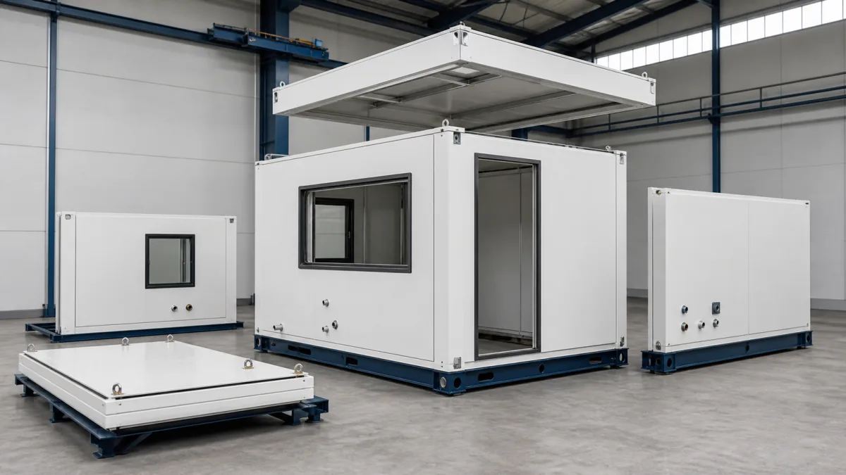
A repeatable module is a section with defined dimensions, structural edges, connection details, and service interfaces that can be reused across multiple booth sizes. Good modularization reduces variation without forcing every project into the same floor plan.
Common approaches include:
| Module approach | Best fit | Main planning concern |
|---|---|---|
| Single-piece booth shell | Compact installations with straightforward transport access | Overall shipping size and lifting method |
| Two-piece or split-shell booth | Larger booths that need manageable shipment dimensions | Weather-tight, repeatable field joint |
| Wall-panel system | Multiple footprints or site access limits | Alignment, stiffness, and field assembly time |
| Base, wall, and roof modules | Projects needing flexible configurations or replacement sections | Clear responsibility for structural connections |
| Pre-fitted room modules | Repeat orders with similar interiors | Control of utility and finish revisions |
Do not divide the booth simply where it looks convenient. Place module joints where they avoid door openings, large windows, high-load equipment, major structural supports, and concentrated water runoff. Each joint needs a documented answer to four questions:
- How are modules located and aligned?
- How are they mechanically fastened?
- How is the joint sealed against water, air, dust, or pests as required?
- How can it be inspected, serviced, or resealed later?
Standardize module dimensions where practical, but avoid treating nominal external dimensions as the only control. The interface drawing should also define mating-face flatness, hole patterns, gasket or sealant locations, connection hardware, and acceptable installation tolerances.
Set transport dimensions before finalizing the layout
Transport is often the hidden constraint in modular FRP booth planning. A design that is efficient in the factory can become costly or difficult to deploy if its width, height, weight, or loading orientation is incompatible with the anticipated route and unloading equipment.
Confirm:
- Maximum shipping envelope for the intended carrier and route
- Whether permits or escorts may be needed for oversized loads
- Overall height when the booth is loaded on its shipping support
- Forklift, crane, telehandler, or truck-mounted crane access at the destination
- Required lifting points, center of gravity marking, and lift angle limitations
- Protection for projecting windows, roof overhangs, counter ledges, and exterior hardware
When deployments may occur at different sites, design to the most restrictive foreseeable route and unloading condition—not only the first destination.
Set Base Lifting and Anchoring Interfaces
The base is the connection between the booth, the transport plan, and the site. It should be specified early because floor construction, anchors, lifting hardware, leveling provisions, utility penetrations, and interior finishes all depend on it.
First, define what supports the booth: a concrete slab, curb, steel frame, elevated platform, trailer chassis, skids, or another engineered foundation. Then establish a base-interface package that identifies:
- Overall footprint and support-point locations
- Required bearing areas and any point-load restrictions
- Anchor locations, hole sizes, edge distances, and hardware type
- Levelness and flatness assumptions for the receiving surface
- Floor elevations at doors, service windows, and accessible entries
- Underfloor utility penetrations and protective sleeves
- Drainage direction around the booth perimeter
- Lifting pockets, lifting lugs, or other approved handling features
Do not assume a flat slab is enough. The site team needs to know where loads are transferred and whether the booth can tolerate shimming, localized support, or small elevation differences. Improper support can affect door alignment, window operation, module joints, and weather sealing.
Lifting interfaces deserve equal attention. A forklift pocket sized for one machine may not suit another fork spacing or capacity. Lift lugs may require a particular sling angle, spreader bar, or lifting sequence. Mark approved lift locations and prohibit lifting from roof edges, window frames, counters, or nonstructural trim.
For repeat deployment, retain the same base bolt pattern whenever possible. If a new footprint is necessary, use a controlled adapter frame rather than casually relocating anchoring points from project to project.
Coordinate Doors, Windows, Counters, and Equipment
Doors, glazing, counters, and installed equipment determine how people use the booth and how the enclosure performs in service. Coordinate them as a package rather than letting each feature be selected independently.
Doors and access
Choose the door location based on safe entry, operator circulation, prevailing weather exposure, and exterior obstructions. Confirm handing, clear opening, threshold detail, closer requirements, locking hardware, panic or emergency egress needs, and whether the door must accommodate carts or service equipment.
A common planning mistake is allowing the door swing to conflict with a workstation, cabinet, or electrical panel. Model the interior with the door fully open and with the expected equipment in place.
Windows and glazing
Glazing should be set by sightlines and exposure, not appearance alone. Map the operator’s view of vehicle lanes, pedestrians, gates, loading areas, and approach paths. Consider glare, solar heat, privacy, security needs, opening windows, pass-through windows, and cleaning access.
For a drive-through or transaction booth, confirm counter height and reach distance relative to the vehicle lane. A counter that is too deep or too high can be difficult for both the attendant and visitor to use. Protect exposed counter edges from impact where carts, vehicles, or frequent package transfers are expected.
Equipment coordination
Prepare an equipment schedule listing each item’s dimensions, mounting method, heat output, service access, power requirement, data connection, and owner-supplied versus booth-supplied status. Include future equipment allowance where changes are likely.
Typical coordination conflicts include:
- A monitor blocking a required sightline
- An access-control panel placed behind furniture
- A printer or cabinet obstructing a door swing
- Camera conduits missing their final locations
- Equipment heat load exceeding the HVAC assumption
- Exterior devices requiring backing plates that were not planned in the FRP shell
Use one coordinated interior elevation for every wall. It is far easier to adjust a drawing than to add unplanned cutouts, reinforcement, or cable routes after molding and finishing.
Plan Electrical, HVAC, and Other Utility Routes
Utilities must have clear entry points, distribution paths, equipment locations, and termination responsibilities. “Rough-in included” is not specific enough for a repeatable booth program.
Create a utility matrix that identifies each service, its entry location, routing path, internal termination, external connection point, and responsible trade.
| Utility | Decisions to confirm |
|---|---|
| Electrical power | Voltage, phase, load estimate, panel location, exterior disconnect needs, receptacle and lighting layout |
| Data and communications | Conduit size, network entry, cable separation, antenna or camera routes, equipment cabinet location |
| HVAC | Cooling and heating loads, equipment location, condensate drainage, service clearance, controls, and exterior penetrations |
| Plumbing | Water, waste, venting, freeze protection, sink location, and underfloor routing |
| Fire and alarm systems | Device locations, conduits, monitoring interface, and site-specific requirements |
| Security systems | Card readers, intercoms, cameras, gate controls, emergency communication, and cable access |
Keep utility penetrations accessible and protected. Penetrations through FRP surfaces should be properly located, reinforced where needed, sealed, and documented. Multiple last-minute holes through exterior walls create avoidable leak paths and make future inspection harder.
For HVAC, do not select unit capacity from booth square footage alone. Internal equipment, solar exposure, glazing area, occupancy, insulation design, door usage, and local climate all affect the load. Verify condensate management, especially where freezing conditions, roof runoff, or pedestrian paths could create problems.
Plan a practical shutoff and service strategy. Operators should be able to reach routine controls, while electrical panels and HVAC service points need enough clearance for qualified maintenance personnel.
Specify Weather Finish and Cleaning Requirements
FRP is often selected for its corrosion resistance and design flexibility, but performance still depends on the resin system, exterior finish, joint design, installation quality, and maintenance conditions. Specify the actual exposure rather than using a generic “outdoor” requirement.
Describe anticipated conditions such as:
- Direct sun and heat cycling
- Wind-driven rain or snow
- Salt air or deicing chemicals
- Industrial dust, oils, or airborne contaminants
- Frequent washdown
- Graffiti risk
- Abrasion from carts, equipment, or vehicle-adjacent use
- Temperature and humidity extremes
The exterior finish specification should address color, gloss range if relevant, UV exposure expectations, cleanability, repair method, and acceptable cosmetic variation. If color matching is important for repeat orders, retain an approved physical or documented color reference; descriptive names alone can be ambiguous.
Also define cleaning restrictions. Some aggressive solvents, abrasive pads, pressure-washing practices, or chemical cleaners may damage finishes, seals, decals, glazing, or caulk joints. A maintenance document should state approved cleaning methods, inspection intervals, and repair procedures for scratches, chips, sealants, and hardware.
Avoid designing roof and wall details that trap water or debris. Sloped surfaces, drip edges, sealed penetrations, and accessible drainage paths are more reliable than depending on frequent maintenance.
Test Assembly, Packing, and Site Installation
The first completed booth should validate the process for every later deployment. Before shipment, conduct a fit-up that confirms module alignment, door operation, glazing condition, joint closure, fastener access, utility routing, and interior equipment clearance.
A practical pre-shipment checklist includes:
- Verify module identification and orientation marks
- Trial-fit all mating components and connection hardware
- Confirm door and operable-window function
- Check that utility penetrations match the coordinated drawings
- Confirm removable panels can be removed with installed equipment nearby
- Photograph packaging condition and label fragile areas
- Package loose hardware by location, not as a mixed assortment
- Include installation drawings, lifting instructions, and sealant requirements
- Identify field-supplied materials separately from shipped materials
Packing should protect surfaces while preserving a logical installation sequence. If the first item needed at the site is buried under another module, installation slows and handling risks increase. Label modules by their final position—such as base, left wall, roof, or front glazing section—and use the same naming convention on the drawings.
Site installation planning should state who provides the foundation, lifting equipment, electrical connection, sealing, anchoring, and final commissioning. It should also define inspection hold points: verify base dimensions before delivery, check levelness before setting modules, inspect joints before interior closeout, and test utilities after connection.
Do not rely on verbal field knowledge for a repeat program. A concise installation method with photos or diagrams can prevent the same assembly error from recurring at multiple sites.
Control Revisions for Repeat Deployments
Repeatable production depends on revision discipline. A booth may look unchanged while small differences in window hardware, panel cutouts, utility entries, anchors, or interior equipment create incompatible parts.
Assign a unique identifier to the overall booth configuration and, where useful, to each repeatable module. Maintain a controlled record containing:
- Approved general arrangement and module drawings
- Bill of materials and finish schedule
- Interface and anchor details
- Door, window, and hardware schedules
- Electrical and utility routing drawings
- Packing and installation instructions
- Approved deviations for individual sites
- Revision history explaining what changed and why
Separate standard configuration from site-specific options. For example, the standard booth may keep the same base, shell, doors, and windows while a site option changes only the electrical entry side, counter opening, or equipment panel. This distinction helps procurement teams compare quotes accurately and prevents a one-time field change from quietly becoming the new default.
Before issuing a repeat order, verify these high-risk items:
- Has the site footprint or anchoring pattern changed?
- Are door handing and vehicle approach direction still correct?
- Are the utility voltage, entry side, and communication requirements the same?
- Has any owner-furnished equipment changed in size, weight, or heat output?
- Does the exterior exposure require a different finish or hardware selection?
- Are transport and lifting conditions unchanged?
- Which drawing revision governs the order?
The most common repeat-order mistake is referring only to a prior purchase order or photos. Use controlled drawings and a written list of confirmed deviations instead.
Build a Better RFQ for a Modular FRP Booth
A complete RFQ shortens clarification cycles and makes competing proposals easier to evaluate. Include the intended use, occupancy, target footprint, transportation limits, base drawing, utility needs, doors and glazing, interior equipment schedule, finish exposure, installation scope, and repeat-order expectations.
For custom fiberglass booths, GFIND can review buyer drawings and application requirements for manufacturability, tooling, prototypes, molded production, finishing, inspection references, and shipment preparation. Review the available portable booth solutions to frame your configuration, then contact GFIND with the drawings, site information, and revision-controlled requirements when you are ready to request project-specific input.