Outdoor FRP Enclosure Specification: A Buyer’s Guide
Learn how to specify an outdoor FRP enclosure for water, dust, corrosion, heat, access, interfaces, loads, finish, and verification in the field.
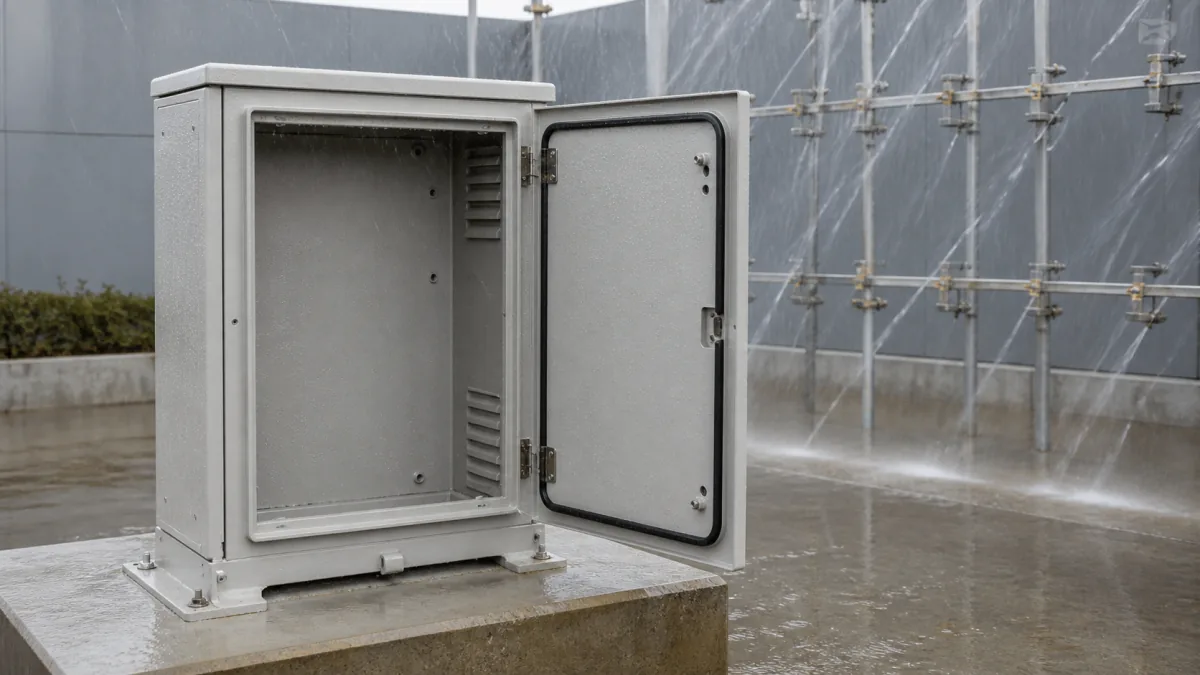
An outdoor FRP enclosure specification should define more than dimensions and color. It needs to identify the equipment being protected, the actual exposure conditions, thermal limits, access needs, interface locations, installation loads, and the evidence required to verify performance.
Fiberglass-reinforced plastic (FRP) can be a practical enclosure material where corrosion resistance, electrical isolation, low maintenance, or lighter handling weight matter. However, the material system, construction, seals, hardware, penetrations, and mounting details must all suit the application. A well-written specification prevents a durable composite shell from becoming the weak point in a system because of poor drainage, unsuitable gaskets, unplanned heat buildup, or inaccessible service components.
Define the Protected Equipment and Site
Start with the equipment, not the enclosure. The enclosure must protect the installed assembly through operation, inspection, repair, and replacement—not merely fit its initial footprint.
Document the following equipment information:
- Overall dimensions, including connectors, handles, hinges, displays, and future accessories
- Equipment weight and center of gravity
- Required clearance around electrical components, heat-producing devices, and serviceable parts
- Operating and storage temperature limits
- Maximum acceptable internal humidity or condensation exposure
- Required cable bend radius and service loop space
- Locations of terminals, disconnects, controls, indicators, antennas, drains, and filters
- Personnel access requirements, including the tools needed for maintenance
Then describe where and how the enclosure will be installed. “Outdoor” is not a complete environmental definition. A roadside communications cabinet, a wastewater pump-station panel, and an agricultural control box may all be outdoors but face very different risks.
Specify whether the enclosure will be:
- Wall mounted, pole mounted, pedestal mounted, rack mounted, or installed on a concrete pad
- Fully exposed to sun and wind or located under a canopy
- Located near salt spray, fertilizer, industrial emissions, vehicle exhaust, or process chemicals
- Subject to washdown, flooding, snow accumulation, wind-driven rain, or airborne dust
- Installed in a public-access location where unauthorized entry or impact is a concern
Buyers evaluating industrial equipment enclosure options should also identify the enclosure’s functional role. Is it a weather cover, a ventilated equipment cabinet, a sealed instrument housing, or a structural support for mounted equipment? Each role changes the appropriate construction and verification approach.
Describe Water, Dust, Corrosion, and UV Exposure
Environmental exposure should be written as specific conditions rather than broad phrases such as “weatherproof” or “corrosion resistant.” These terms are useful goals, but they do not tell an enclosure manufacturer how to select resin, gasket material, drainage features, hardware, or penetration details.
Define the water exposure
State the source, direction, frequency, and pressure of water exposure. Consider:
- Ordinary rainfall and wind-driven rain
- Direct hose washdown or pressure-cleaning practices
- Splashing from vehicles, process equipment, or irrigation
- Standing water around the base
- Temporary submersion or flood exposure
- Ice, snowmelt, and freeze-thaw cycles
A door seam that performs acceptably in vertical rainfall may not perform the same way under horizontal spray or repeated washdown. Specify roof overhangs, sloped surfaces, drip edges, raised bases, and drainage paths where they are needed. Do not rely on a perimeter gasket alone to manage water.
Define dust and particulate exposure
Fine dust can enter through louvers, cable entries, door gaps, and imperfect seals. It can also reduce cooling performance by coating screens, heat exchangers, and internal components.
Identify the dust source and expected maintenance conditions. Examples include mineral dust, road dust, agricultural debris, wood fibers, conductive particles, or metal-processing residue. If filtered ventilation is necessary, specify the filter access method and acceptable replacement procedure. A filter that requires removing the cabinet from its mount is unlikely to be maintained consistently.
Match materials to corrosion conditions
FRP construction can offer good resistance to many corrosive environments, but performance depends on the resin system, fiber architecture, surface protection, fasteners, hinges, latches, inserts, and accessories. The enclosure body is only one part of the corrosion system.
For corrosive locations, describe:
- Chemicals or contaminants that may contact the enclosure
- Approximate concentration, temperature, and exposure duration, if known
- Salt air, deicing salts, fertilizer, wastewater gases, or industrial vapor exposure
- Whether contamination is airborne, intermittent splash, continuous contact, or washdown residue
- Required hardware material and whether dissimilar-metal contact must be managed
If the environment includes an unknown or changing chemical mixture, state that uncertainty in the RFQ. A supplier can then identify material questions that need resolution rather than assuming a generic exterior-grade laminate is suitable.
Account for sunlight and appearance retention
UV exposure affects exterior appearance and may affect surface condition over time. Specify the intended finish: molded color, gel coat, paint, protective coating, or another agreed exterior surface. Include the required color reference, gloss expectations if relevant, and whether cosmetic variation is acceptable on non-visible surfaces.
Dark colors can increase solar heat gain. If internal temperature is constrained, color selection is a thermal decision as well as an aesthetic one.
Resolve Heat, Ventilation, and Condensation
An enclosure can keep rain out and still create a reliability problem by trapping heat or moisture. Treat temperature, airflow, and condensation as a combined design issue.
Begin with a heat budget. List the heat dissipated by internal equipment at normal and maximum operating conditions, along with the allowable internal temperature range. Then identify the site’s expected ambient temperature range, direct solar exposure, and whether the enclosure is shaded or mounted near other heat sources.
The primary thermal approaches have different tradeoffs:
| Approach | Best fit | Key specification considerations |
|---|---|---|
| Sealed enclosure | Equipment must be isolated from dust, moisture, or contaminants | Internal heat must be managed without open airflow; define cooling equipment, thermal paths, and condensate handling |
| Passive ventilation | Moderate heat load and relatively clean environment | Define louver placement, insect screens, filters, water-shedding design, and maintenance access |
| Filtered forced ventilation | Higher heat load where filtered air is acceptable | Define airflow target, fan duty, power source, filter service interval, alarms, and replacement access |
| Air conditioning or heat exchanger | High heat load or tight temperature control | Define heat load, ambient conditions, power consumption constraints, condensate routing, and service clearances |
| Heater or anti-condensation control | Cold, humid, or rapidly changing conditions | Define control setpoints, heater capacity, clearances, and protection against condensation on sensitive components |
Do not assume that ventilation automatically solves overheating. Airflow paths must move past heat-generating components and exit without recirculating hot air. Likewise, a fully sealed enclosure can experience condensation when internal surfaces fall below the dew point after temperature changes.
Specify whether the enclosure needs:
- Insulation or a radiant barrier
- Solar shielding, a double roof, or a sunshade
- Internal fans, louvers, filters, or cooling equipment
- Condensate drains or breathable membrane vents
- Hygrostats, thermostats, dew-point monitoring, or alarm points
- Segregated compartments for power electronics and sensitive instrumentation
Where appearance or instrument protection is a priority, review the design considerations used for an FRP outdoor instrument housing, including the relationship between access, sealing, and environmental exposure.
Plan Doors, Panels, Seals, and Maintenance Access
The most important enclosure features are often the ones opened, removed, or serviced. Doors, removable panels, gaskets, latches, hinges, and access covers should be specified around real maintenance tasks.
Define the required access method:
- Single door, double door, lift-off cover, hinged lid, removable panel, or bolted service cover
- Door swing direction and maximum opening angle
- Clearance around the installed location for opening doors and removing components
- Number and location of access points
- Whether one person must be able to open, hold, and service the enclosure
- Requirements for hold-open hardware, door stops, or safety restraints
Specify the service activities that must occur inside the enclosure. A technician may need to replace a fuse, read a display, reset a breaker, connect a laptop, change a filter, or remove an instrument module. Each task requires different sight lines, reach distances, lighting, and clearances.
For seals, identify the environmental function rather than naming a gasket material without context. State whether the seal must resist rain, washdown, dust, UV exposure, temperature cycling, chemicals, compression set, or repeated door opening. Confirm how the gasket will be retained, where joints occur, and how damaged seals can be replaced.
Common mistakes include:
- Specifying a narrow door that prevents component replacement
- Locating latches where they interfere with a nearby wall or pole
- Omitting a drip edge above a gasketed opening
- Using a removable panel where frequent service is expected
- Requiring a high sealing level while adding uncontrolled field-cut openings
- Forgetting internal clearance for cable loops and door-mounted components
Security requirements should also be explicit. Identify the latch type, lock provision, keying responsibility, tamper-resistant hardware needs, and whether access must be limited to authorized personnel. Avoid treating “lockable” as a complete requirement.
Locate Cable, Pipe, and Mounting Interfaces
Every cutout, cable entry, pipe penetration, and mounting point can affect sealing, structural behavior, and installation time. Provide an interface drawing whenever possible.
For cable and conduit entries, define:
- Quantity, nominal size, and location of entries
- Entry orientation: bottom, side, rear, roof, or door
- Cable diameter range and minimum bend radius
- Conduit type, gland type, strain-relief needs, and sealing expectations
- Whether entries are factory machined, field drilled, or left blank
- Grounding or bonding provisions where applicable to the installed system
- Separation requirements between power, control, communications, and fiber cables
Bottom entries can reduce direct rain exposure but need drainage planning and enough internal room for cable routing. Side entries may improve installation access but can be more exposed to wind-driven rain. Roof entries should be used only when the penetration design and water-shedding details support the actual environment.
Mounting interfaces need the same level of definition. Provide hole patterns, bracket geometry, support-member locations, fastener types if assigned, and allowable fastener torque if inserts are used. If the enclosure attaches to an existing steel frame, concrete pad, pole, or equipment skid, include the mating drawing and installation orientation.
Do not assume a flat panel can accept concentrated mounting loads anywhere. Composite laminates may require reinforced zones, embedded plates, backing structures, or load-spreading brackets. These details should be designed before production rather than improvised during installation.
Set Structural, Handling, and Installation Loads
An outdoor enclosure must withstand more than the static weight of its equipment. The specification should identify the loads it experiences during shipment, lifting, mounting, service, wind exposure, and normal use.
At minimum, describe:
- Empty enclosure weight target, if handling limits exist
- Installed equipment weight and center of gravity
- Maximum door, panel, or roof-mounted accessory load
- Mounting orientation and support locations
- Wind exposure and projected accessory area
- Snow, ice, or debris loading where relevant
- Personnel contact loads, leaning loads, or accidental impact concerns
- Lifting points, forklift pockets, or manual handling needs
- Shipping restraint points and packaging constraints
If lifting is required, state whether the enclosure will be lifted empty, partially assembled, or fully populated with equipment. Lifting a bare shell is substantially different from lifting an enclosure with batteries, transformers, or rack-mounted electronics inside.
Also distinguish between operational loads and installation loads. A cabinet may be structurally adequate once secured to a foundation but vulnerable while being transported or lifted by an unapproved edge. Require clear handling instructions when the geometry or center of gravity makes incorrect lifting likely.
For doors and hinged components, specify the maximum supported load in the open position, expected operating cycles if known, and whether wind can act on an open door. Door restraints may be needed in exposed locations to prevent hinge damage or injury.
Reference Ratings Only With a Verification Plan
A rating or standard reference can be useful, but only when the exact requirement and verification method are agreed. Avoid placing a generic rating label in an RFQ without defining what it applies to and how conformity will be evaluated.
For example, an IP code and a NEMA enclosure type address environmental protection concepts, but they are not interchangeable shorthand. Their applicability depends on the referenced edition, the complete installed assembly, and the relevant test conditions. An enclosure body may perform differently after adding field-installed cable glands, fans, windows, locks, or cooling equipment.
When a rating is required, specify:
- The exact standard or rating designation and applicable edition, if controlled by the project.
- Whether the requirement applies to the bare enclosure, factory-configured assembly, or final installed system.
- All penetrations, accessories, and mounting orientations included in the verification.
- The acceptance evidence required, such as inspection records, dimensional checks, functional checks, or a defined test procedure.
- The responsible party for testing and the point in the project when verification occurs.
- Any samples, witness requirements, or agreed acceptance criteria.
A practical verification plan may also cover visual finish, dimensions, door fit, gasket continuity, hardware operation, interface locations, mounting-hole alignment, and agreed material or construction references. Verification should reflect the actual risks of the project rather than adding vague requirements that cannot be objectively checked.
Prepare an Outdoor Enclosure RFQ Checklist
A complete RFQ gives suppliers enough information to identify design decisions, provide meaningful feedback, and avoid assumptions. Attach drawings, photos of the installation site, equipment layouts, and interface documents where available.
Use this checklist before issuing an outdoor FRP enclosure RFQ:
- Application: Equipment function, installation location, service environment, and expected operating life assumptions.
- Dimensions: External envelope, internal clearances, reserved future space, and allowable tolerances.
- Equipment: Weight, heat output, center of gravity, operating limits, service tasks, and internal layout.
- Environment: Rain, washdown, dust, UV, salt, chemicals, temperature range, humidity, flooding, wind, snow, and impact risks.
- Construction: Preferred FRP process if required, resin or chemical-resistance needs, reinforcement zones, and surface finish expectations.
- Thermal control: Heat load, ventilation strategy, filters, fans, cooling equipment, insulation, heaters, drainage, and controls.
- Access: Door or panel arrangement, swing direction, hinges, latches, locks, gasket needs, and maintenance clearances.
- Interfaces: Cable entries, pipe penetrations, glands, vents, displays, antennas, mounting points, brackets, and grounding provisions.
- Structural needs: Installation supports, equipment loads, lifting method, transport restraints, wind exposure, and open-door loads.
- Appearance: Color reference, gloss range if needed, texture, logo areas, visible-surface expectations, and acceptable cosmetic variation.
- Verification: Drawings for approval, inspection points, dimensions to check, functional checks, required test references, and acceptance criteria.
- Commercial details: Required quantity, prototype needs, packaging constraints, delivery destination, and documentation format.
For custom projects, GFIND can review buyer drawings and application requirements for manufacturability, tooling, prototype needs, molded production, finishing, inspection to agreed references, and shipment preparation. When your checklist and drawings are ready, use the project contact form to discuss the enclosure requirements and confirm which details need engineering review.