Custom Carbon Fiber Robot Links
Tubular carbon links suit robot and parallel-mechanism projects where moving mass and axial stiffness are design priorities. We make bare members or fitted links to your approved component construction, coordinating tube section, laminate, joint spacing and end engagement. Individual links or matched pairs can be supplied with the specified spherical or clevis fittings.
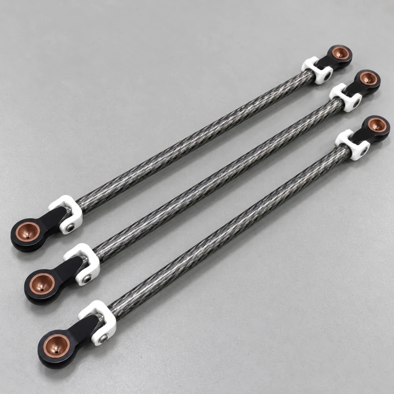
Three carbon robotic arm links with spherical cup joints and fork fittings at both ends.
Image credit: ·
Robot link connections
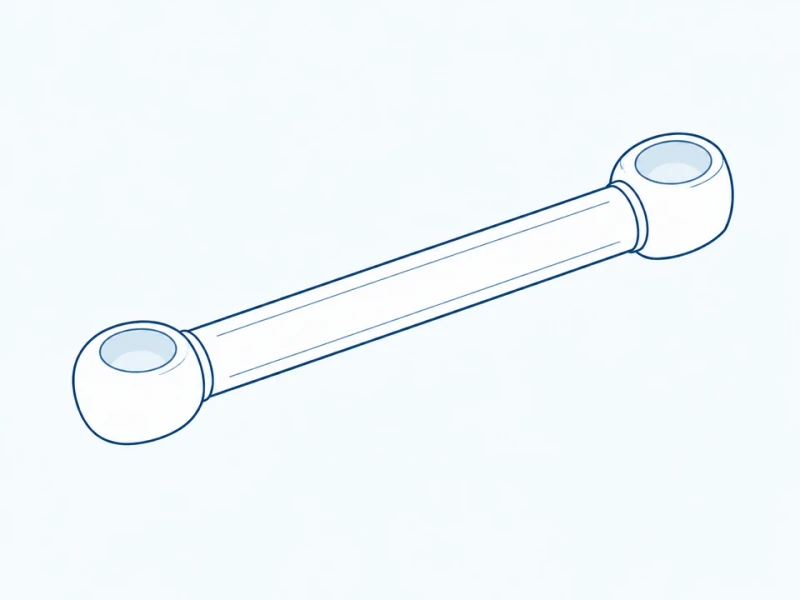
Tube with spherical joint fittings
Spherical joint cups at both ends connect the carbon tube to the mechanism's ball joints.
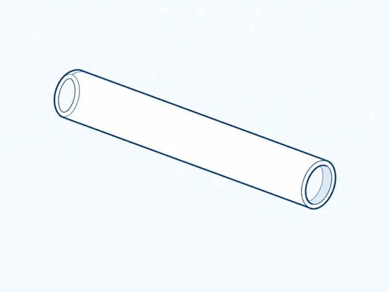
Bare tubular link
A bare carbon tube provides the link body for separate end fittings and joints.
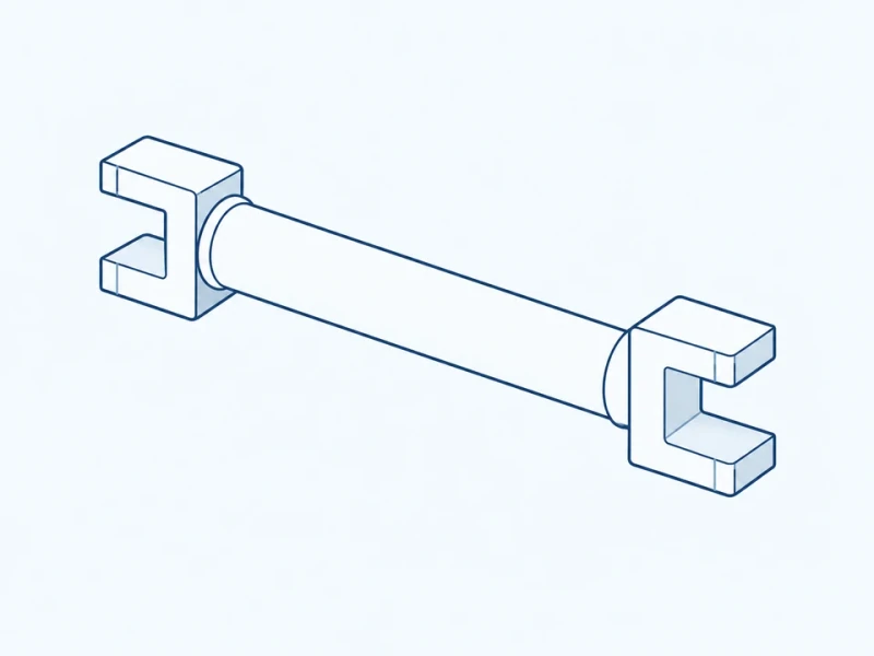
Clevis-ended arm link
Forked clevis ends connect the tube to pivot pins, with each fork oriented to its joint axis.
Matched parallel link pair
The two links have matched joint-center distances and fitting orientation, for parallel linkages.
Robot links made to your mechanism
Link section and construction
Tube size, wall construction and fiber orientation follow the approved link drawing and its load and stiffness requirements, together with the specified joint-center distance.
Tube and end-fitting assembly
Choose bare members or links with the specified spherical or clevis ends. Tube engagement, joining method and fitting orientation are defined together for the supplied assembly.
Matched link pairs
The paired links are made to the same joint-center distance and fitting orientation.
Link geometry and end fittings
Joint spacing and tube section
Joint-center distance runs between the two marked joint axes. The section below shows the tube walls inserted into the fitting. Engagement is measured from the socket mouth to the inserted tube end.
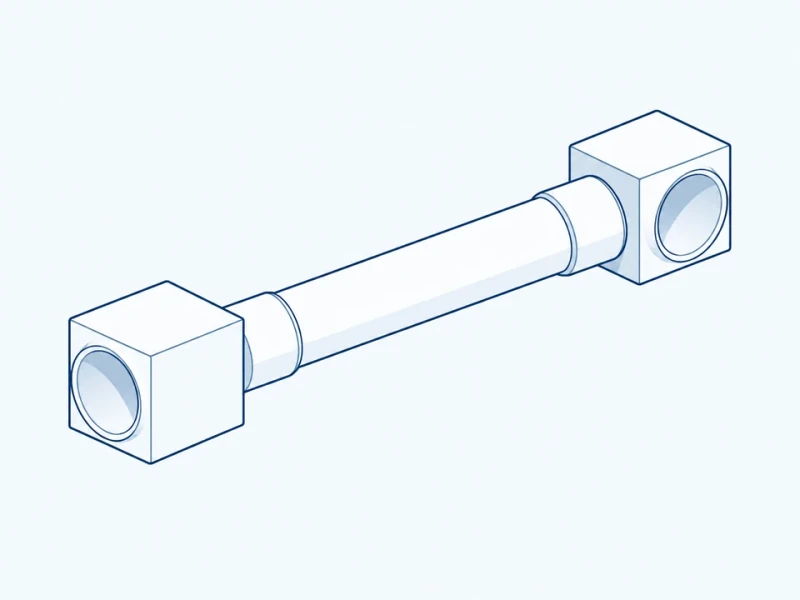
Tube-to-fitting connection
The tube-to-fitting connection joins the carbon member to the end hardware. Fitting orientation determines how the two joint axes relate to one another.