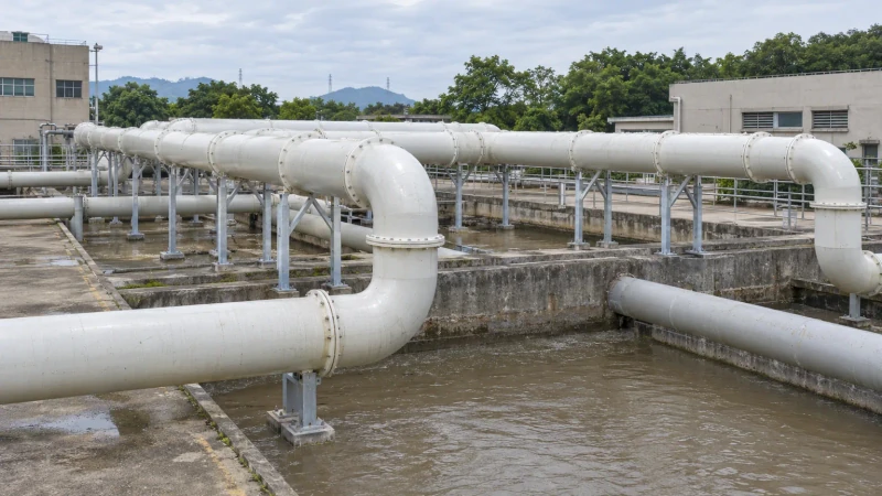
Duct sections prepared for the surveyed extraction route.
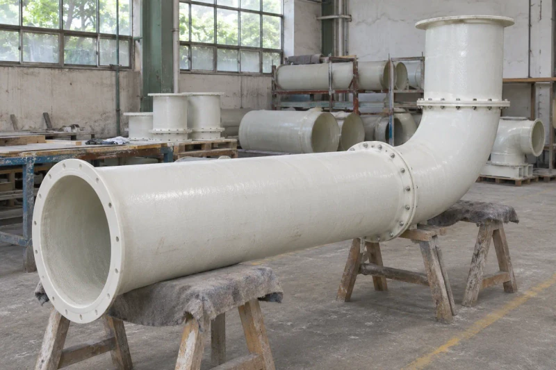
Custom straight ducts, elbows and flanged connections fabricated around your wastewater-site layout and the equipment they connect to.
Bends, flange orientations and joint positions follow the equipment connections and site handling limits.
- We make
- Straight ducts and bends
- We coordinate
- Flanged site connections
- You receive
- Route and support planning
Connect pickup points across changing elevations.
An extraction route above wastewater tanks must connect several pickup points while following the site's elevations and access spaces. Bends, flange positions and section lengths need to suit both the equipment connections and the available support locations.
Several pickup points at different elevations
The extraction route has to connect equipment while respecting the site geometry.
Construction for the exhaust duty
The specified air stream and pressure or vacuum determine the duct and joint requirements.
Sections that can be delivered and joined
Lengths and flange positions need to work with supports, access and the installation sequence.
How we customize the parts.
Route and connection geometry
Duct diameters, bend angles and flange orientations follow the surveyed route and equipment drawings. Changes in elevation are resolved in the section schedule before fabrication.
Construction for the exhaust stream
The air composition, temperature and pressure or vacuum determine the duct construction. Joint details follow the system designer's requirements.
Sections the site team can handle
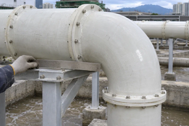
Joint positions account for support contacts, fastening access and delivery limits. Section divisions are considered with your installation team, including the order in which connections will be made.
Fabricate to the released drawings
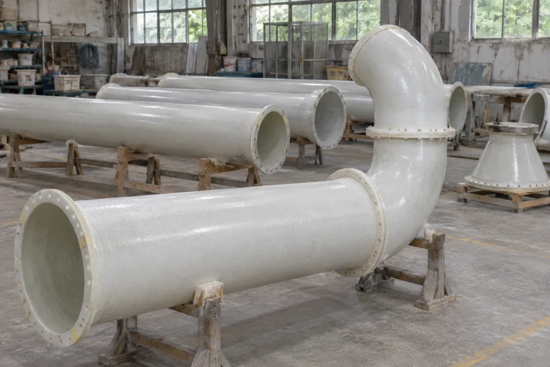
We make the straight runs and shaped connections, then prepare their specified joining faces. Dimensions and connection angles are checked against the individual component drawings. The ordered sections are identified and protected for transport. Packing and delivery groups follow the agreed handling limits and installation sequence.
A section schedule for the installation team.
The section schedule brings surveyed elevations and connection orientations into one installation reference. Prepared joints and handling divisions help the site team plan the order of fitting around supports and equipment.
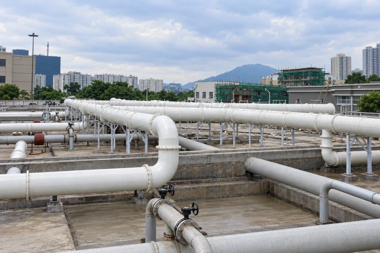
Sections follow the surveyed route
Bends and elevations match the equipment connection layout.
Joint access included
Flange positions account for supports and fastening space.
Handling divisions already planned
Section lengths follow delivery limits and the installation sequence.
Dimensions and design options
- Product family
- FRP Corrosive Exhaust & Odor-Control Ducts
- Production basis
- Approved drawing or sample
- Product scope
- Duct sections, elbows, branches and flanged connections
- Operating duty
- Reviewed from gas composition and temperature
- Layout
- Project-defined ventilation route
Exhaust duct sections
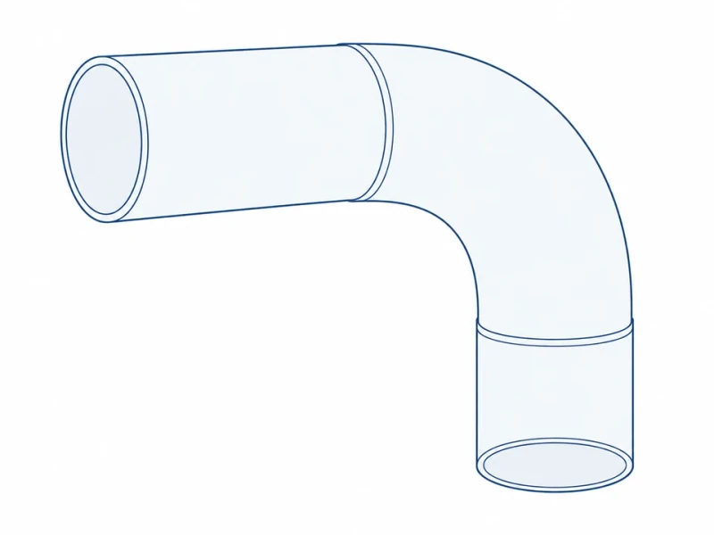
Round duct with elbow
A round elbow turns the exhaust line around equipment.
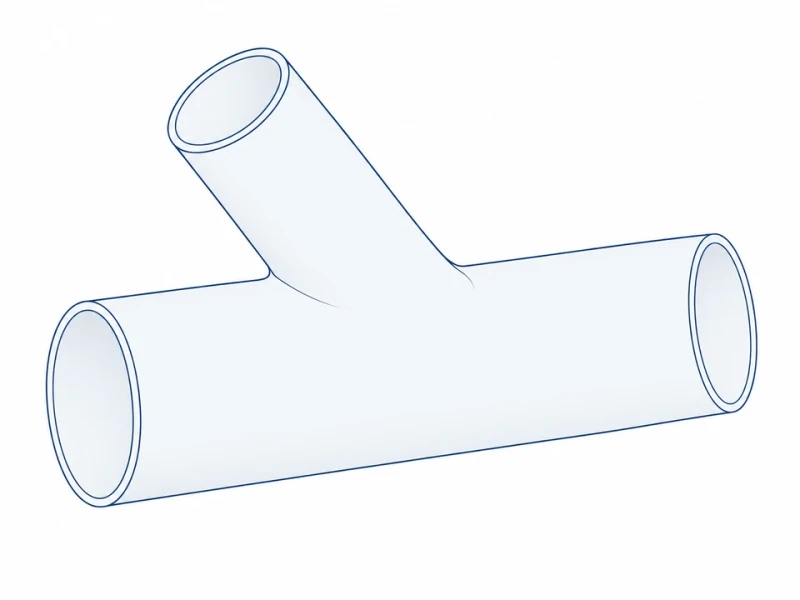
Collection branch
An angled branch connects a local extraction point to the main duct.
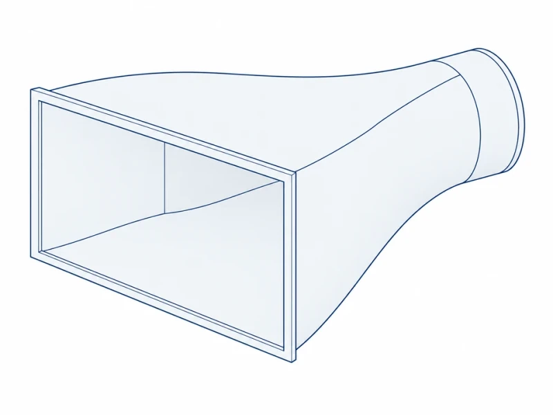
Rectangular transition
A tapered section joins a rectangular outlet to round ductwork.
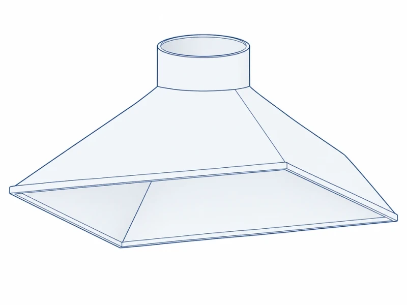
Collection hood
A wide hood tapers up to a smaller round duct to collect exhaust at the source.
Custom duct sizes and connections
Run length and bore
Run length, bore and support spacing follow your exhaust route and the separate support layout.
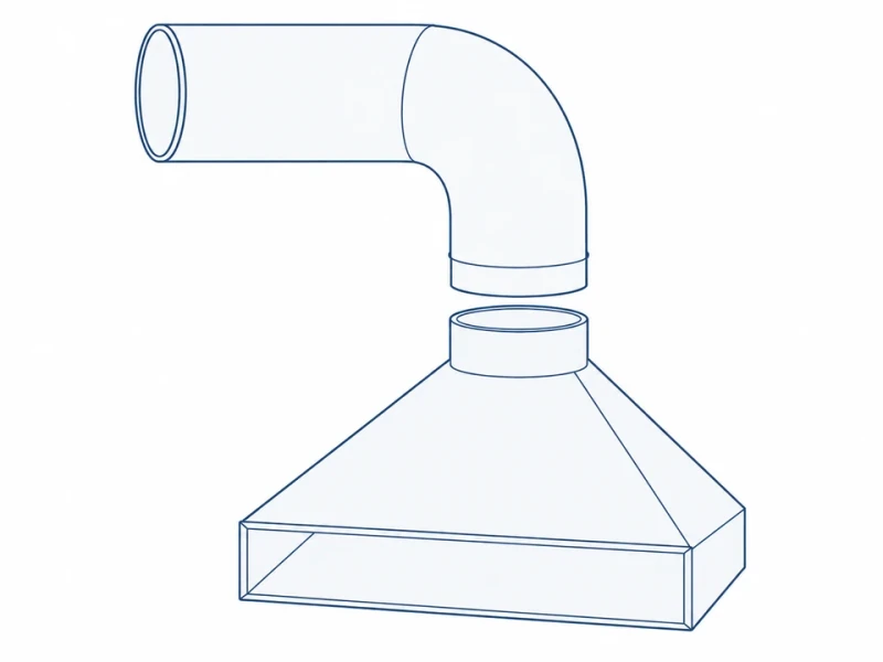
Elbow and collection hood
Elbows and tapered hoods are sized to connect the duct run to your equipment opening.