Pipe bends that meet the route at both ends.
Custom fiberglass pipes, bends and branches with construction and flange connections selected for the operating conditions you specify.
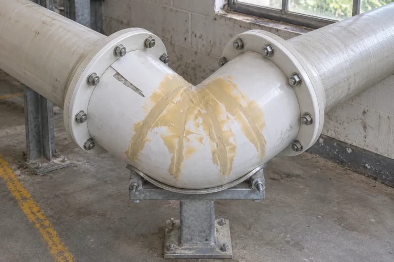
Bend geometry and flange orientation are considered together, reducing separate adjustments during fit-up.
- Components
- Pipes, bends and branches
- Materials
- Duty-specific materials
- Connections
- Flanged or drawing-defined interfaces
Connect fixed equipment positions through a changing route.
Process pipework often has to turn between fixed equipment connections while leaving space for supports and assembly. A bend needs the right overall dimensions, but its flange positions and bolt orientation are just as important to the fit.
Fixed connections at both ends
Overall length alone does not settle a bend. Both mating faces need to arrive at the right position and angle.
Supports and bolting space
A route that fits on a drawing still needs room to handle the section and reach the connections.
The actual process exposure
Resin and barrier construction depend on the specified medium, concentration and operating range.
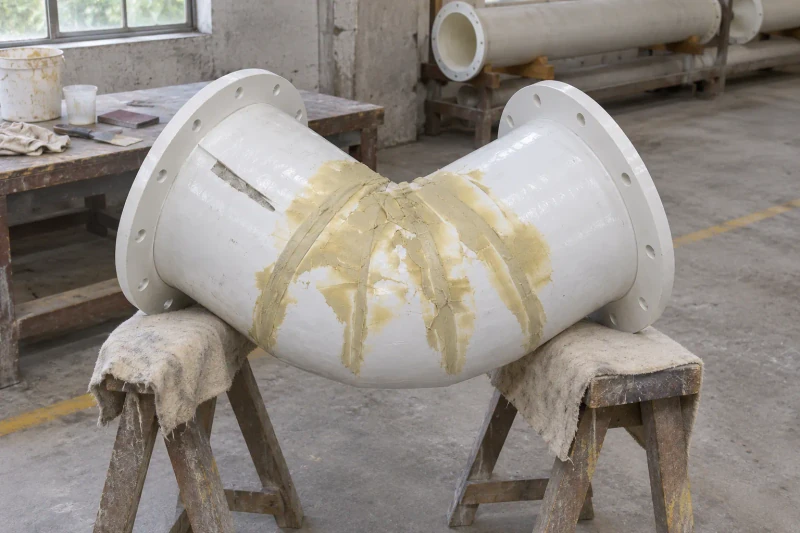
How we customize the parts.
Construction for the process fluid
The resin and inner barrier are selected for the actual media, concentration and operating range you specify.
Bends that meet both pipe ends
Bend dimensions and straight lengths follow the route drawing. Space around the component accounts for the planned support positions and the chosen assembly method.
Flanges in the right orientation
Flange sizes, mating faces and bolt patterns follow the connection schedule. Both ends are considered together so their relative angle matches the surrounding pipework.
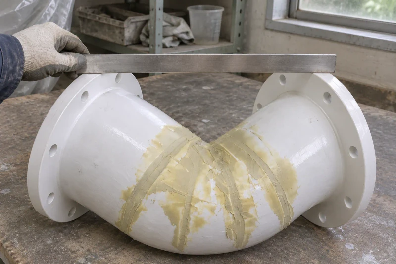
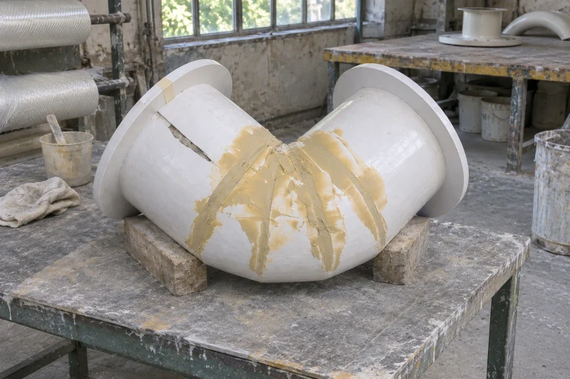
Fabricate the scheduled components
We make the pipes, bends or branches to the selected construction, complete the specified joint work and prepare the flange faces and drilling. Flange alignment and dimensions are checked against the drawings. Any specified pressure or leak inspection follows the agreed acceptance plan before flange faces are protected for packing.
Less guesswork at the pipe connections.
The route drawing carries the bend dimensions and relative flange positions together. Fit-up can follow a defined connection arrangement instead of treating each pipe end as a separate decision.
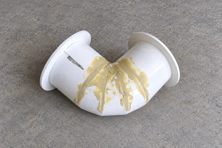
Both ends considered together
Bend dimensions and flange orientation share the same route reference.
Assembly access planned
Joint positions account for fastening space and the selected supports.
Construction tied to the duty
The specified medium and operating range guide resin and barrier selection.
Dimensions and design options
- Inspection
- Dimensional checks; pressure or leak tests as specified
- Production basis
- Approved drawing or sample
- Scope
- Pipes, elbows, flanges and fittings
- Construction
- Selected for your media, pressure and temperature
Process-pipe fitting options
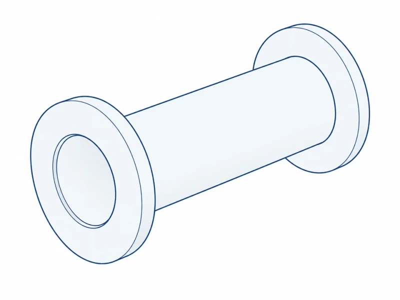
Flanged straight spool
A straight pipe section joins two equipment faces with flanges at both ends.
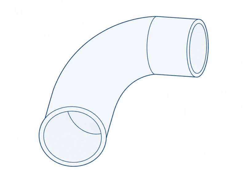
Swept elbow
A swept bend changes pipe direction with the required radius and end lengths.
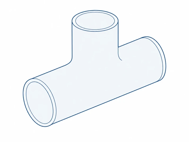
Branch tee
A tee adds a branch connection to the main process line.
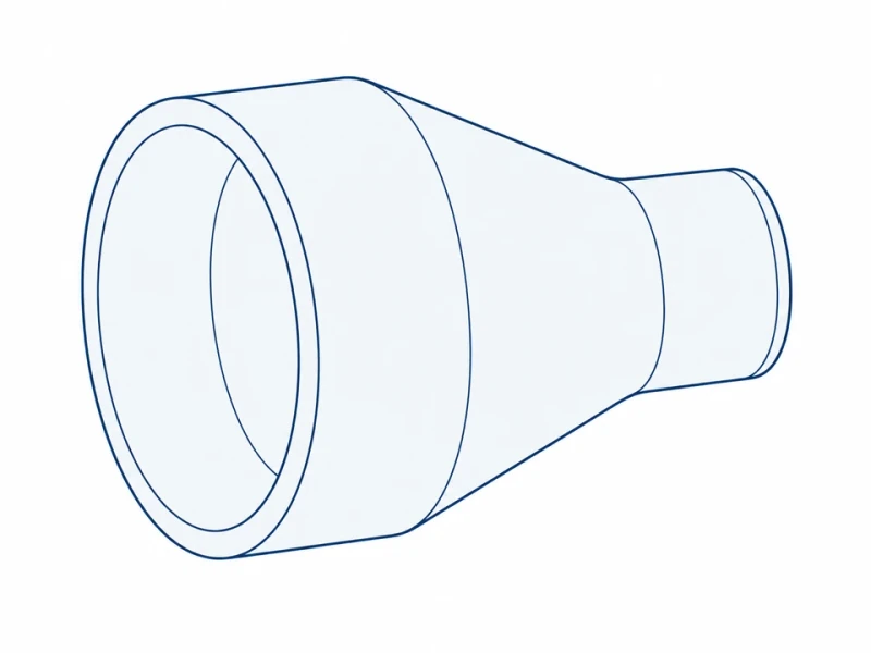
Diameter transition
Reducers join different pipe bores in concentric or offset arrangements.
Custom bores and flange dimensions
Flange connection dimensions
Flange diameter, fixing centers and working bore are made to match your mating flange.
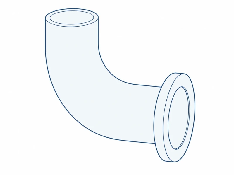
Curved elbow and end flange
Elbow radius, pipe bore and flange shape are made to your route and connection drawing.