A slurry tank that fits the process room.
Fiberglass process tanks with a rectangular ribbed body, specified lining and connection positions developed around your slurry duty and equipment-room layout.
The vessel envelope, process connections and cleaning access are coordinated before fabrication.
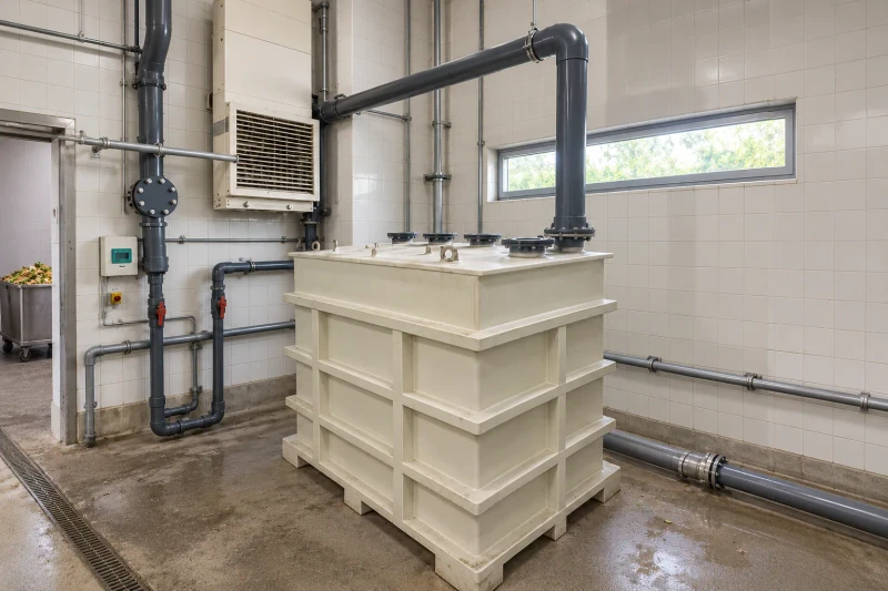
- Tank
- Rectangular slurry vessel
- Connections
- Nozzles placed to your process pipework
- Construction
- Duty-specific construction
Fit the working volume around the room and pipework.
A food-waste process room brings the storage tank close to pipework, equipment and access routes. The working volume must fit the available space without leaving the cleaning points or pipe connections difficult to reach.
Working volume in a crowded room
The tank must fit its process space and the delivery route without blocking maintenance access.
Slurry conditions at the inner surface
Contents, solids and temperature determine the lining and shell construction required.
Connections carrying external loads
Nozzles need the correct positions and a defined arrangement for supporting the adjoining pipes.
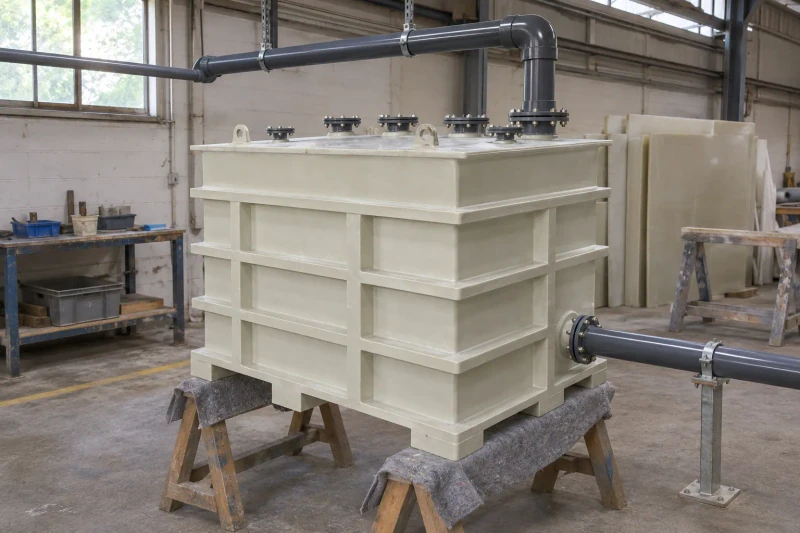
How we customize the parts.
Construction for the slurry
Contents, solids, temperature and any pressure or vacuum determine the lining and shell construction we propose. The rib layout and supports are set together with the working level and tank dimensions.
Connections for the process equipment
Nozzle sizes and positions follow your pipework layout. We also agree how the external pipes are supported, so their loads at the nozzles are accounted for.
Access inside the room
Inspection and cleaning openings are placed where your maintenance team can reach them. Tank size is checked against the delivery route and the space needed to set it in place.
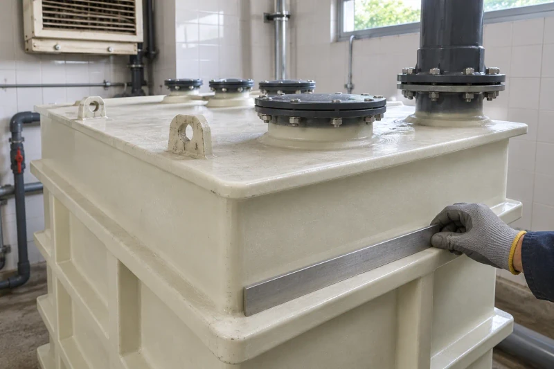
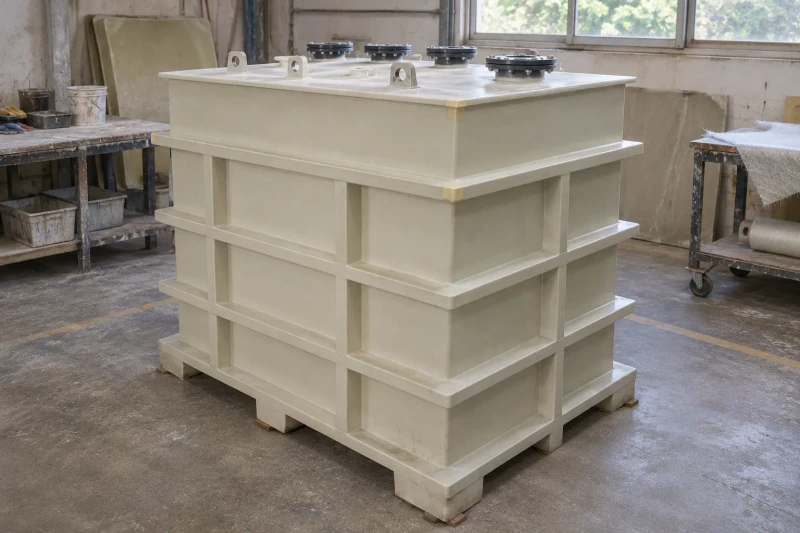
Build the tank and openings
We build the rectangular tank with its specified lining and rib reinforcement, then prepare the nozzles and inspection openings to the agreed drawings. We carry out the agreed dimensional and leak checks, then pack the tank for the access route and handling method confirmed with your equipment integrator.
Connections and access in the tank drawing.
The vessel drawing carries the room envelope, nozzle positions and cleaning access together. The equipment team can coordinate surrounding pipework and support details before the tank is placed in the room.
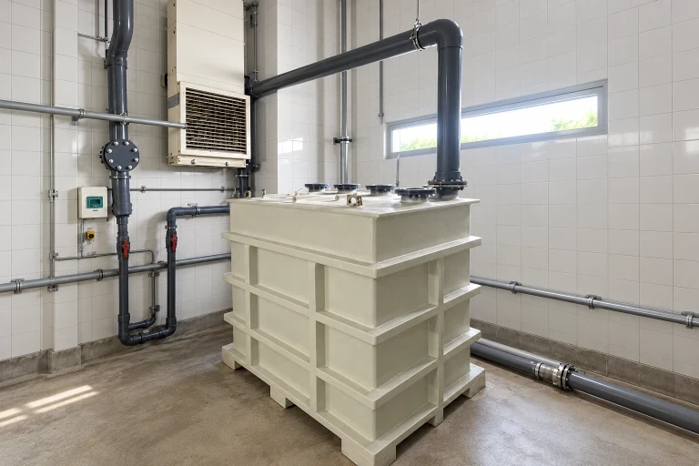
Connections positioned with the room
Nozzle locations follow the adjoining process-equipment layout.
Cleaning access included
Inspection openings remain part of the vessel arrangement.
The delivery route considered
Tank dimensions are reviewed against the space available for placement.
Dimensions and design options
- Product family
- Custom FRP Wastewater & Slurry Tanks
- Production basis
- Approved drawing or sample
- Material
- FRP, with resin and lining chosen for the liquid
- Application
- Wastewater or slurry storage
- Dimensions
- Sized to working volume and plant space
Wastewater-tank configurations
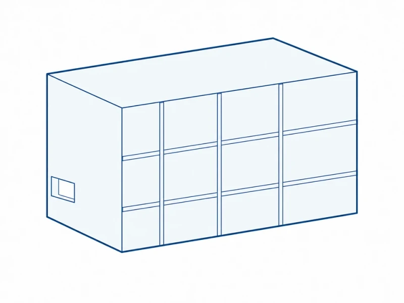
Reinforced rectangular shell
A rectangular tank with external ribs makes good use of limited plant space, with walls and base built for the specified loads.
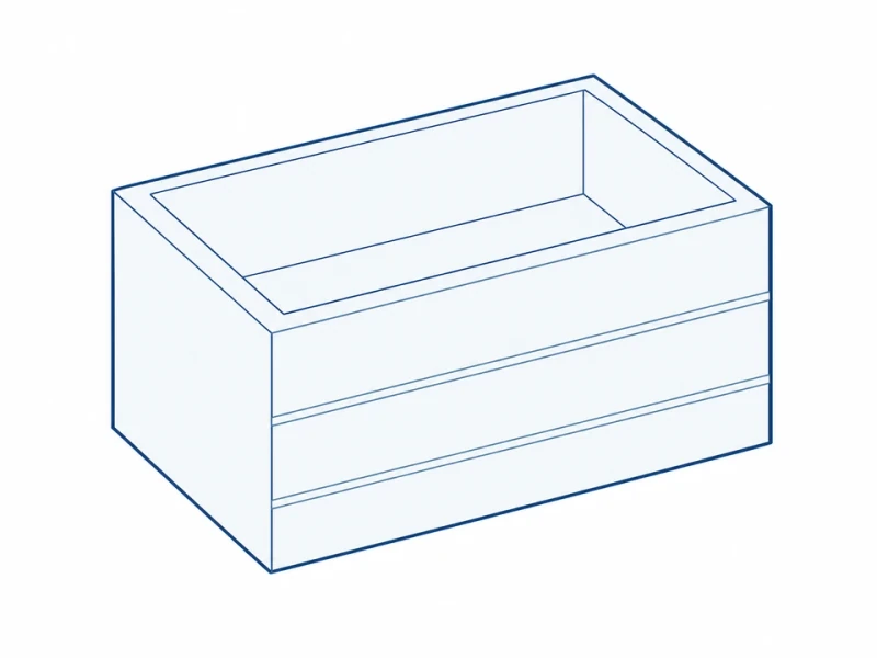
Open cleaning access
An open top or large removable cover gives access to the tank interior for cleaning.
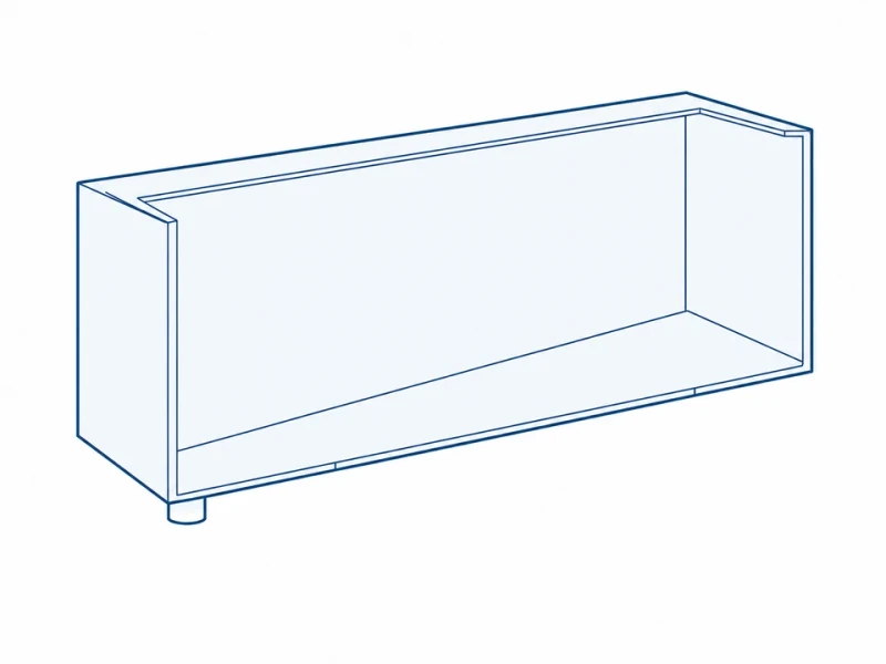
Sloping-bottom outlet
A bottom sloping to a low outlet helps settled solids drain out, with supports shaped to the tank underside.
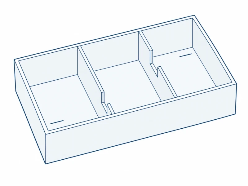
Defined internal compartments
Internal partitions and overflow passages divide the tank into the zones set by your process designer.
Tank levels and pipe connection
Tank width and operating level
Tank width is measured across the body. The liquid-level line and pipe centerline use the outside base as their height datum; working depth and volume also depend on the inner floor and lining.
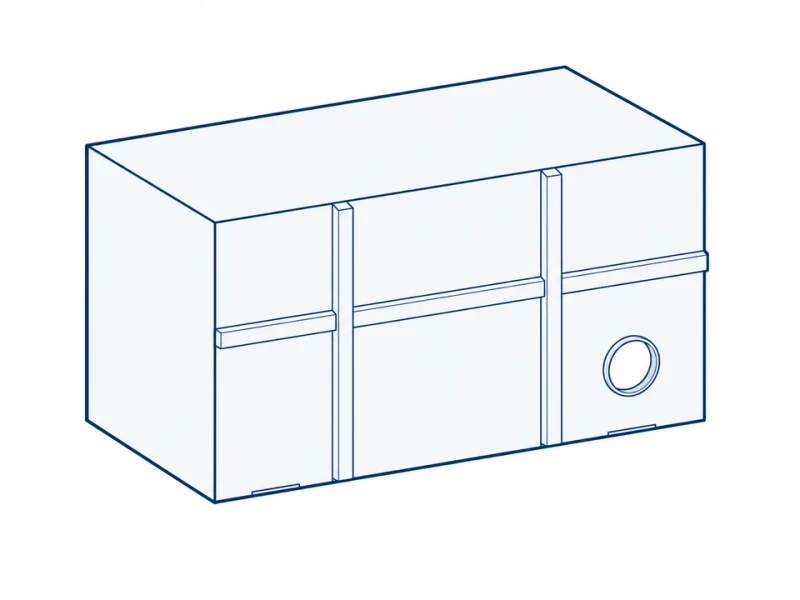
Reinforced walls and side connection
The rectangular tank walls, reinforcement positions and side pipe opening can suit your liquid-handling and support design.