Water storage shaped around a restricted space.
We develop the tank body around the available length, width and height, then add the reinforcing ribs, top access and pipe connections your installation needs.
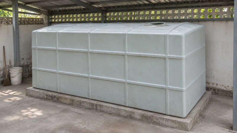
The rectangular body combines the available footprint with reinforcing ribs, top access and planned pipe connections.
- We make
- Rectangular molded body
- We coordinate
- Agreed openings and ribs
- You receive
- Support and delivery planning
Keep useful storage inside a fixed envelope.
The storage area has a fixed footprint and limited height. A long rectangular body uses that space, while a top opening leaves access for inspection and cleaning.
Storage inside a fixed footprint
Length, width and height have to accommodate the working volume and the available installation space.
Support for the filled tank
Shell construction and external ribs need to suit the specified water load and base support.
Access and pipework around the body
The top opening and water connections must remain usable after the tank is placed.
How we customize the parts.
A body sized to the space
Length, width and height are set together with the working volume and the delivery opening the tank must pass through.
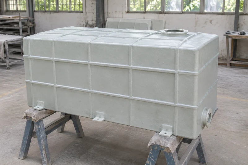
External reinforcing ribs
The shell and rib layout are built for the stored water and the base support on your project.
Access from above
The top opening stays reachable for inspection and cleaning, while inlet, outlet and drain positions follow your pipe layout.
Fabricate the ribbed shell
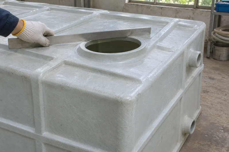
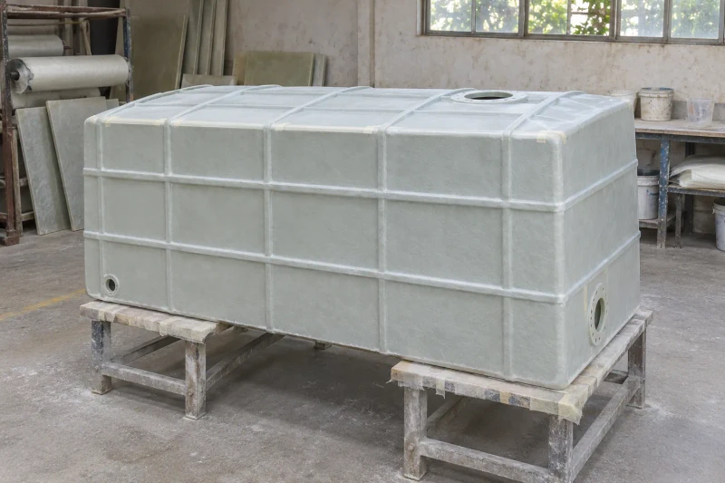
We form the tank body, add the reinforcement and prepare the connection openings or nozzles. Dimensions and connection positions are checked against the drawing. Leak testing can be included in the order.
The volume and its connections in one drawing.
The tank outline, ribs and openings follow one released arrangement. The site team can coordinate the support base and water connections with that envelope while keeping the top access reachable.
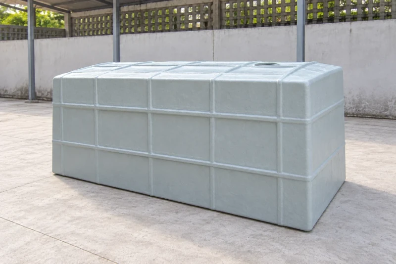
The footprint used deliberately
Body dimensions relate the working volume to the available space.
Openings in one tank drawing
Top access and water connections are positioned together.
A defined base-support arrangement
The tank shell and ribs follow the specified filled-vessel support.
Reserve-water storage sized to the site plan.
Custom cylindrical fiberglass tanks sized for the required water reserve, with openings and handling preparation matched to the site arrangement.
Working volume, draw-off connections and delivery constraints guide the tank body together.
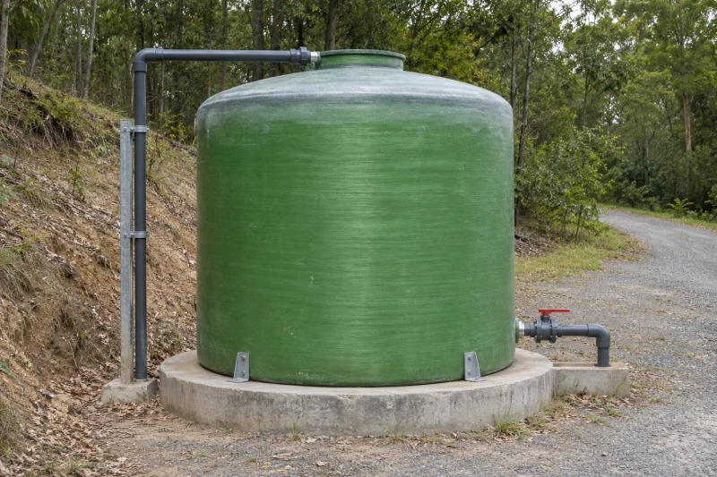
- Tank
- Cylindrical water tank
- Connections
- Inlet, outlet, access and supports to your drawing
- Use
- Site-specific storage duty
Bring the storage requirement and the site limits together.
A forest-fire water plan needs an agreed reserve and a way to refill and draw from it. The storage vessel must fit the site, the foundation arrangement and the route available for delivery and unloading.
An agreed usable water reserve
The working volume and draw-off requirements have to guide the vessel dimensions.
Refill and withdrawal connections
Inlet, outlet, vent and overflow positions must suit the separately specified site equipment.
A filled vessel on a real site
Foundation contacts, road access and unloading limits constrain the tank arrangement.
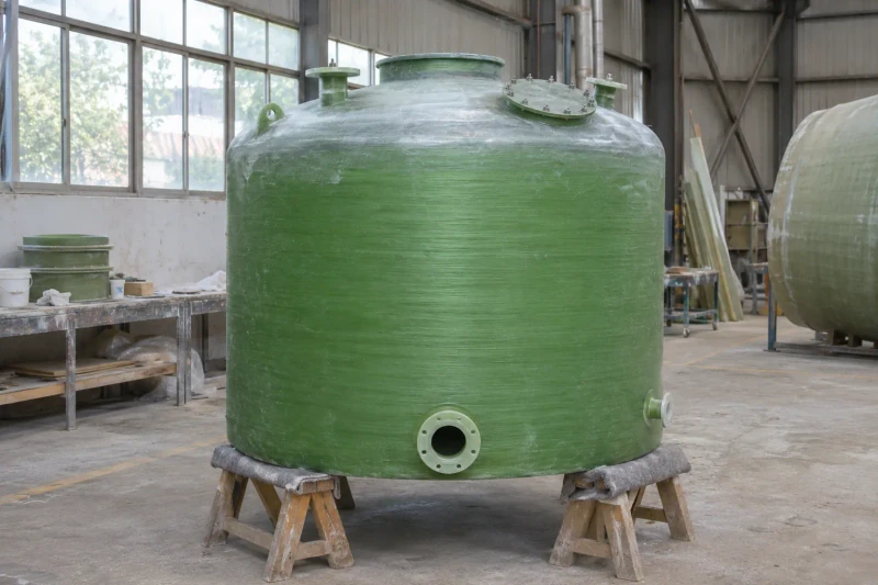
How we customize the parts.
Usable reserve and draw-off
Tank dimensions come from the working volume and draw-off you need. The tank is sized for the storage duty in your site plan, not an assumed firefighting capacity.
Refill, outlet and access points
Inlet, outlet, vent, overflow and access openings are scheduled to suit your refill equipment and any stated pressure or vacuum conditions.
Foundation and transport limits
The shell and base are built for how the filled tank will be supported. Road access, unloading space and handling limits are checked before the outline is fixed.
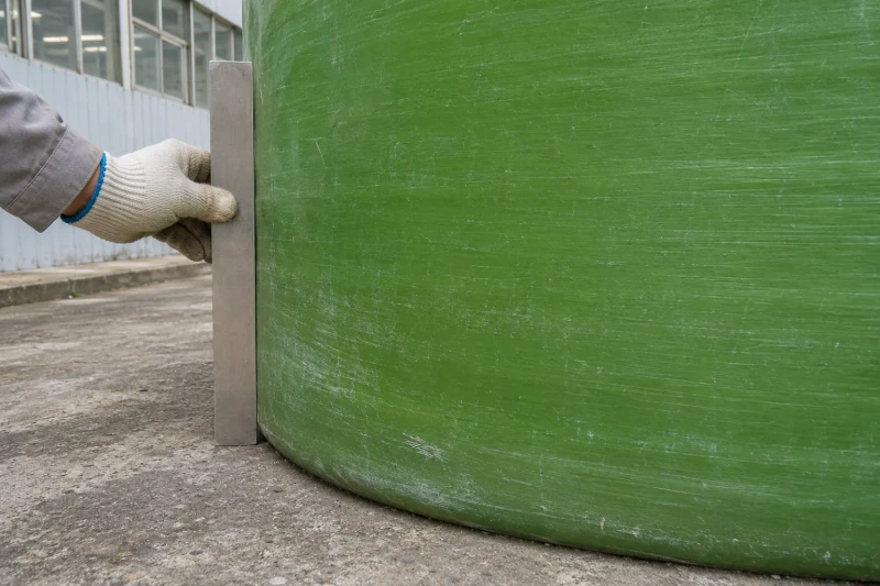
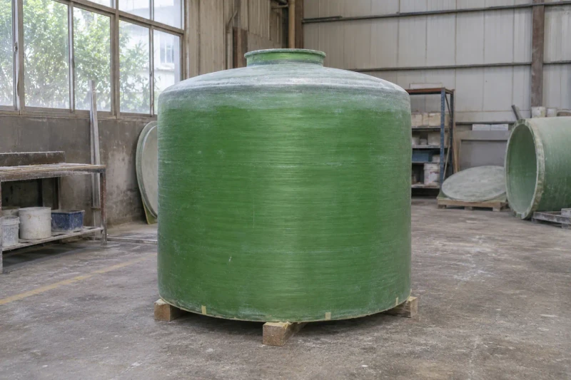
Build the cylindrical tank
We build the shell, rounded shoulder and base to the agreed construction, then prepare the scheduled openings and any fittings listed in the order. We complete the agreed dimensional and leak checks, then plan handling around the route and the unloading responsibilities confirmed for your site.
A vessel with defined site connections.
The tank envelope and connection schedule give the site team a defined vessel to coordinate with the foundation, refill equipment and draw-off system. Delivery access is considered before the body outline is fixed.
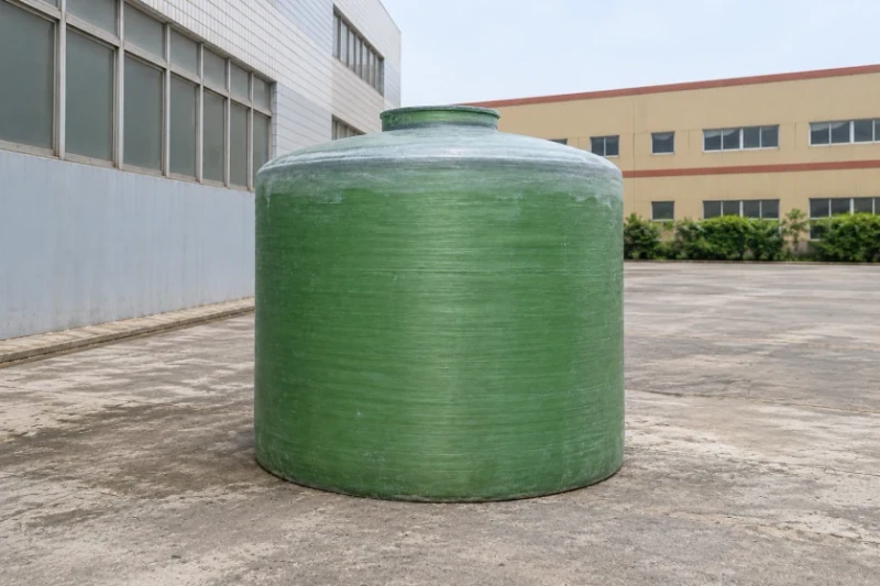
Storage tied to the water plan
Working reserve and draw-off needs guide the vessel dimensions.
Defined connection positions
Refill and withdrawal equipment can be coordinated around the tank drawing.
Delivery and base contacts planned
Road access, unloading and filled-tank support are considered together.
Dimensions and design options
- Product family
- Custom FRP Water Tanks
- Production basis
- Approved drawing or sample
- Reference water-bowser tank size
- 3000 × 1850 × 1300 mm
- Reference wall build
- 5 mm FRP + 9 mm board + 1 mm FRP
Water-tank configurations
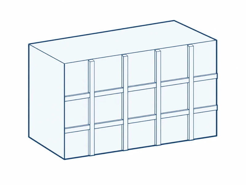
Reinforced rectangular tank
A rectangular shell has external reinforcing ribs for fixed storage within a restricted footprint.
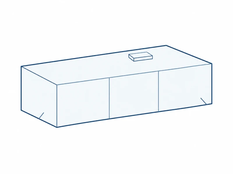
Low vehicle-mounted shell
A low-profile tank follows the vehicle frame, with baffles and restraints specified for vehicle loads.
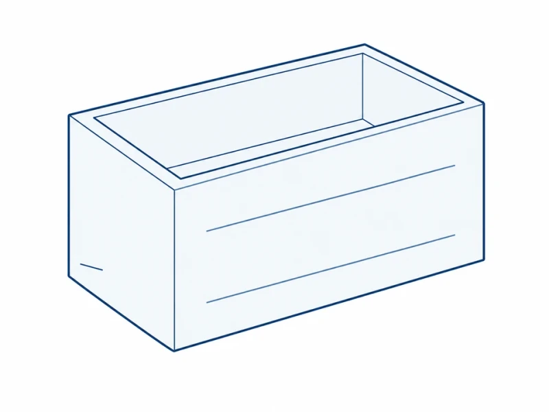
Open-top utility tank
An open top leaves the interior accessible for utility use and tank cleaning.
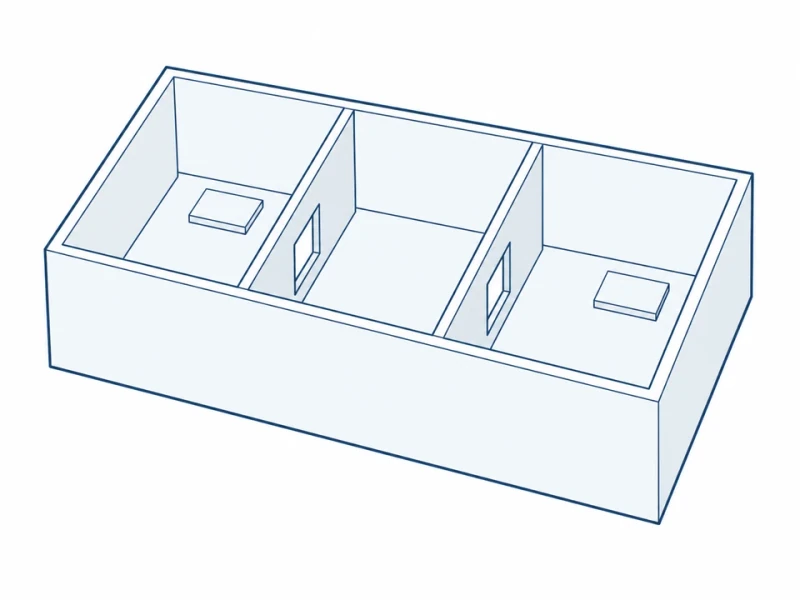
Divided tank interior
Internal partitions create connected or separate water compartments, with openings for cleaning each section.
Water tank size and nozzle height
Tank envelope and water connections
The elevation measures the outside width and height of a rectangular tank body. Nozzle height runs from the outside base to the connection centerline. Working capacity also depends on wall construction, freeboard and any internal partitions.
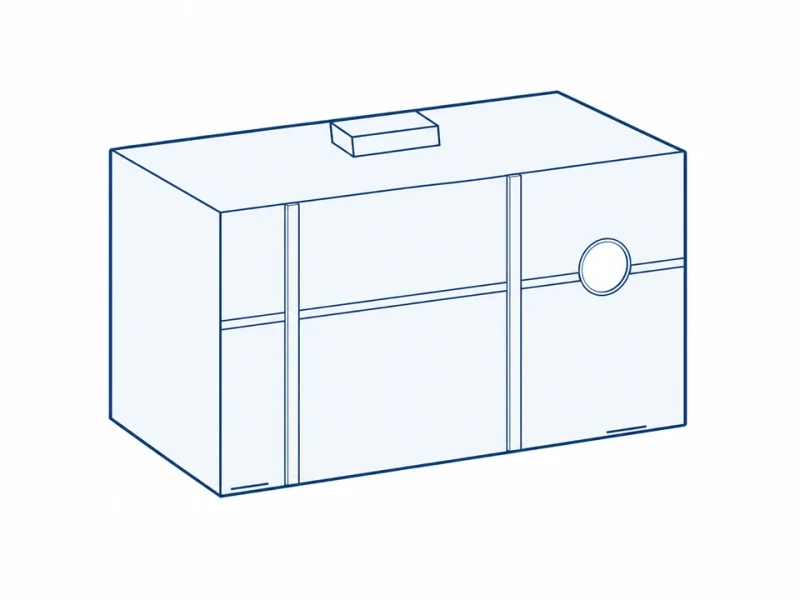
Top access and reinforced walls
Top access size, wall reinforcement and side connection positions can follow your tank and piping design.