Carbon Fiber vs Fiberglass: Custom Part Selection
Compare carbon fiber and fiberglass for custom parts by load, weight, damage, finish, insulation, tooling, and cost before you specify a laminate.
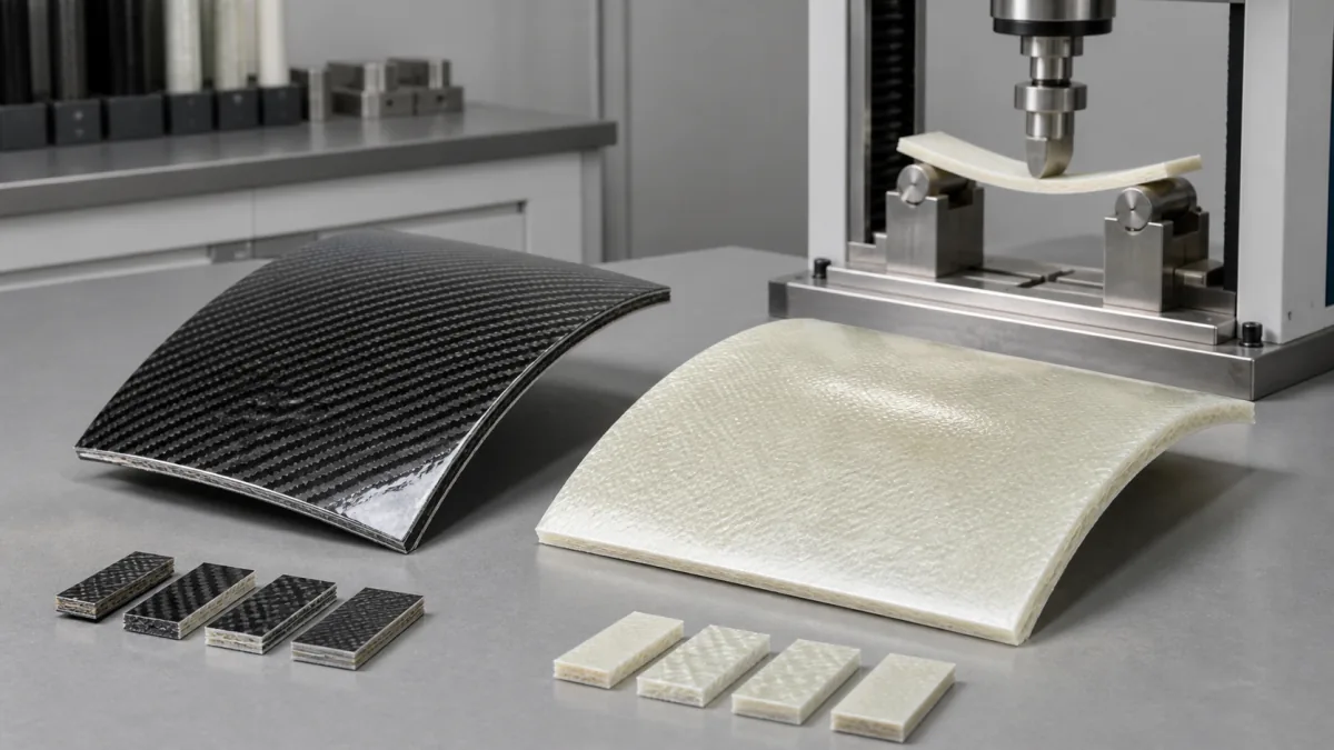
Carbon fiber and fiberglass can both make capable custom composite parts, but neither is automatically “better.” Carbon fiber is usually selected when high stiffness, low weight, dimensional control, or a visible woven finish matters. Fiberglass is often the more practical choice when impact tolerance, electrical insulation, cost control, and forgiving fabrication are higher priorities.
For a custom part, the right comparison is not simply carbon fiber versus fiberglass. It is the proposed laminate, geometry, load path, attachment method, environment, finish requirement, manufacturing process, and acceptable failure mode. A thin carbon laminate may outperform a thicker glass laminate in stiffness, while a well-designed fiberglass part may be the smarter solution for a housing, panel, cover, enclosure, or impact-prone component.
Begin With Loads, Interfaces, and Failure Consequences
Start material selection by defining what the part must do, not by choosing a fiber based on appearance or a general strength claim.
Identify the primary loads:
- Bending: A panel, bracket, fairing, or cover that must resist deflection.
- Tension or compression: A structural member that carries direct pull or push loads.
- Torsion: A tube, arm, frame element, or enclosure that twists in service.
- Repeated loading: Vibration, cyclic motion, opening and closing, or pressure pulses.
- Impact: Dropped tools, road debris, handling damage, collisions, or accidental strikes.
- Environmental loading: Moisture, UV exposure, chemicals, heat, cold, and thermal cycling.
Then define the interfaces. Fasteners, bonded joints, metal inserts, hinges, latches, mounting feet, and cutouts often determine whether a composite design succeeds. Concentrated loads can cause crushing, bearing damage, delamination, or cracking even when the overall panel is strong.
Failure consequences also matter. A cosmetic trim panel that develops a surface crack has a different design target than a guard, equipment cover, electrical enclosure, or load-bearing component. For higher-consequence applications, the design should establish allowable deflection, acceptable damage, inspection criteria, and the validation method before production material is released.
A supplier should receive the service loads or design assumptions, mounting details, clearance requirements, and any known failure concerns along with the drawing. That allows the laminate and local reinforcements to be evaluated as part of the component—not as a generic material choice.
Compare Stiffness, Weight, and Part Thickness
Carbon fiber generally provides greater stiffness than fiberglass at a comparable laminate construction. In practical terms, a carbon-fiber part can often meet a deflection target with less material thickness or less mass than a fiberglass alternative. That can be especially valuable in long, flat, slender, or cantilevered parts where bending stiffness drives the design.
Fiberglass is less stiff, but that does not make it unsuitable for structural work. Designers can increase laminate thickness, add ribs, use a sandwich core, change the section shape, or add localized reinforcements. A shaped fiberglass component may meet performance requirements efficiently without needing carbon fiber.
| Selection factor | Carbon fiber | Fiberglass |
|---|---|---|
| Stiffness | Typically higher | Typically lower, but can be improved with geometry and thickness |
| Part weight | Often lower for a stiffness-driven design | May require more material to reach the same stiffness |
| Impact response | Can retain hidden internal damage after impact | Often more visibly forgiving, depending on laminate |
| Electrical behavior | Generally conductive | Generally electrically insulating |
| Cosmetic appearance | Woven carbon can be a desired visual feature | Can be painted, gel-coated, or finished in many ways |
| Material cost | Usually higher | Usually lower |
| Design flexibility | Strong option for lightweight, stiff structures | Strong option for cost-conscious and insulation-focused applications |
Weight should be evaluated at the part level, not only through fiber density. A carbon laminate may allow a thinner wall, but the final mass also includes core material, resin, inserts, coatings, fasteners, ribs, and overlap zones. Conversely, a fiberglass design with a well-placed core or closed section can provide substantial stiffness without becoming excessively heavy.
Part thickness affects more than stiffness. It can change clearances, attachment geometry, hardware length, molding complexity, edge finishing, and heat transfer. Do not specify a fiber type first and assume the same thickness will work. Ask for the thickness range, laminate schedule, and reinforcement approach needed to satisfy the actual load and deflection requirements.
For a broader look at how fiberglass can support lightweight design, see how fiberglass helps reduce weight without sacrificing strength.
Strength Is Not a Single Number
“Carbon fiber is stronger than fiberglass” is too broad to guide a purchase decision. Composite performance depends on fiber orientation, fiber content, resin system, cure method, thickness, voids, part geometry, load direction, holes, and edge details.
A unidirectional carbon laminate can be exceptionally effective along the fiber direction but may need additional reinforcement for transverse loading, shear, or impact. A woven fiberglass laminate may offer more balanced behavior in multiple directions. The relevant question is: What load must the finished part carry, in which direction, for how long, and with what safety margin?
Consider Impact Damage and Repair Strategy
Impact behavior is a major separator in carbon fiber vs fiberglass for custom parts. Composite damage is not always obvious. A surface may look intact while the laminate beneath it has experienced delamination, fiber breakage, matrix cracking, or core damage.
Carbon fiber is valued for stiffness, but an impact event may produce damage that is less visually apparent than the underlying structural condition. That makes inspection planning important for panels or components exposed to impact, tool drops, transport damage, or service abuse.
Fiberglass often provides more visible evidence of damage, such as whitening, cracking, or fiber exposure. This can be useful in applications where a quick visual inspection is part of routine maintenance. However, fiberglass can also sustain internal damage, so visible appearance alone should never be the only acceptance criterion.
Before choosing either material, establish:
- Expected impact sources and energy levels, if known
- Whether cosmetic damage is acceptable
- Whether the component must continue operating after a minor impact
- How damage will be found: visual inspection, tap testing, dimensional checks, or another agreed method
- Whether field repair is realistic or replacement is preferred
- Whether a repair changes appearance, stiffness, electrical behavior, or certification obligations
Repairs to either material can involve removing damaged laminate, tapering the repair area, rebuilding plies, curing the patch, and refinishing the surface. A repair may be practical for a noncritical panel, but it may not restore the original appearance or precisely reproduce the original laminate. For critical parts, define repair limits and replacement criteria during design review rather than after damage occurs.
Review Surface Appearance and Cosmetic Weave
A visible carbon weave is a finish choice, not proof of structural quality. Cosmetic carbon skins can be used over another structural laminate, while a structural carbon laminate may not produce a flawless show surface without appropriate tooling, resin control, and finishing.
If appearance matters, specify the visual standard in concrete terms:
- Visible carbon weave, painted finish, gel coat, or textured surface
- Gloss level and color expectation
- Acceptable weave alignment and pattern distortion
- Acceptable pinholes, print-through, seams, edge transitions, and surface marks
- Which face or faces are cosmetic
- Whether the part will be viewed at arm’s length or from a normal installed distance
- Sample, photo reference, or approved master part for inspection
Carbon’s woven appearance can help differentiate a premium consumer-facing or motorsports-style component, but it can also create sourcing constraints. Curved corners, deep draws, abrupt thickness changes, and complex geometry may distort the weave. A painted carbon part may provide the stiffness benefit without the visual challenges of an exposed weave.
Fiberglass offers considerable finish flexibility. It can be gel-coated, painted, textured, or made with a surface veil to improve appearance. For industrial covers, housings, and access panels, a durable painted or molded finish may be more functional than a clear-coated woven carbon surface.
Check Electrical, Thermal, and Galvanic Factors
Carbon fiber is electrically conductive enough to require deliberate design around electrical systems and metal interfaces. Fiberglass is generally electrically insulating, which makes it a frequent choice for electrical enclosures, isolation barriers, antenna-adjacent structures, and applications where conductivity would create an unwanted path.
When using carbon fiber, check:
- Whether the part could contact energized components or wiring
- Grounding and bonding requirements
- Potential interference with antennas, sensors, or radio-frequency equipment
- Isolation requirements around fasteners, connectors, and mounting hardware
- Lightning, static, or electrical discharge considerations where applicable
Carbon fiber can also create galvanic corrosion concerns when it directly contacts certain metals in the presence of an electrolyte such as moisture or saltwater. Aluminum is a common concern. The specific risk depends on the metals, coating systems, exposure conditions, electrical continuity, and joint design.
Potential controls include nonconductive isolation layers, suitable coatings, sealed joints, isolated fasteners, and drainage that prevents trapped moisture. Do not assume a paint layer alone will solve the issue; review the full interface and likely service environment.
Thermal behavior also differs. Carbon fiber laminates can conduct heat and electricity along the fiber network, while fiberglass laminates are generally more insulating. Resin systems have their own service-temperature limits, and elevated temperature can affect stiffness, strength, finish durability, and bonded joints. Specify the continuous and peak operating temperatures, as well as hot-side and cold-side exposure conditions.
Compare Tooling, Process, and Volume Requirements
The fiber choice influences manufacturing, but process selection is equally important. A custom part may be produced using open molding, resin infusion, vacuum-bagged layup, compression molding, prepreg processing, resin transfer methods, or other approaches. The suitable process depends on geometry, cosmetic requirements, repeatability needs, target volume, inspection requirements, and budget.
Tooling should be considered early because it affects:
- Surface quality and cosmetic side definition
- Dimensional consistency
- Draft and demolding feasibility
- Parting lines and flange placement
- Insert placement and secondary operations
- Cycle time expectations
- Prototype-to-production transition
- Tool maintenance and replacement strategy
For low-volume prototypes, a simpler tool may be appropriate if it produces representative geometry and allows the laminate to be evaluated. For repeated production, more robust tooling may be justified when surface quality, dimensional control, and repeatability are important.
Carbon fiber can increase material and handling costs, especially where cosmetic orientation, controlled resin content, or specific cure methods are needed. Fiberglass often offers more economical material options and can be a better match for large covers, housings, and general-purpose molded components. Still, the lowest raw-material cost is not always the lowest finished-part cost. A heavier fiberglass part may require redesign of brackets or hardware, while a carbon part may need electrical isolation, more exact cosmetic controls, or more expensive tooling.
For projects considering custom carbon structures, review GFIND’s carbon-fiber component options in the context of your own drawing, laminate requirements, and application conditions.
Avoid Choosing Material by Marketing Claims
Several common shortcuts create avoidable project risk.
“Carbon is always stronger.”
Carbon is often the better option for stiffness-driven designs, but the finished part’s performance depends on the engineered laminate and interfaces. A poorly designed carbon part can underperform a properly designed fiberglass part.
“Fiberglass is only for low-end parts.”
Fiberglass is a capable engineering material for many structural, electrical, chemical, transportation, and industrial uses. It is not merely a budget substitute.
“A visible weave means it is carbon throughout.”
A cosmetic carbon layer does not reveal the full laminate construction. If fiber content or structural construction matters, define it in the specification.
“Same shape means the same material can be swapped.”
Changing from fiberglass to carbon—or the reverse—may require different thickness, attachment reinforcements, isolation details, and validation testing.
“One coupon result qualifies the part.”
Flat test coupons can provide useful material data, but they do not fully represent holes, bonded inserts, corners, curved surfaces, edge loads, or production variation.
A better RFQ describes performance and acceptance conditions rather than requesting a material name alone. Include drawings, estimated annual quantity, target weight if applicable, loading information, mounting hardware, cosmetic requirements, environmental exposure, and the inspection or validation expected before release.
Create a Material Decision Checklist
Use this checklist before specifying carbon fiber or fiberglass for a custom part:
- Define the function. Is the part primarily structural, cosmetic, protective, electrical, thermal, or a combination?
- Map the loads. Identify bending, tension, compression, torsion, vibration, pressure, and impact conditions.
- Set limits. Document allowable deflection, target weight, required stiffness, and acceptable damage.
- Review interfaces. Show fasteners, inserts, bonds, metal contact points, cutouts, and load-transfer areas.
- Check the environment. Include moisture, salt, chemicals, UV, temperature range, and cleaning methods.
- Address electrical behavior. Determine whether conductivity, insulation, grounding, antenna performance, or galvanic isolation affects the choice.
- Choose the appearance level. Separate structural requirements from visible weave, paint, gloss, color, and texture requirements.
- Plan for impact and repair. Decide how damage will be identified, whether repair is allowed, and when replacement is necessary.
- Align process and volume. Confirm prototype needs, expected production quantity, tooling expectations, and dimensional tolerances.
- Define validation. Agree on fit checks, load testing, environmental exposure, cosmetic approval, and inspection references appropriate to the application.
Carbon fiber is often the right answer when low mass and high stiffness justify its additional cost and electrical design considerations. Fiberglass is often the better answer when insulation, impact practicality, finish flexibility, and budget are central. Hybrid laminates may also be worth evaluating when a project needs carbon stiffness in selected areas and fiberglass isolation or toughness elsewhere.
For a custom-part review, GFIND can work from buyer drawings and application requirements to assess manufacturability, tooling, prototypes, molded production, finishing, inspection references, and shipment preparation. When you have defined your key loads, interfaces, and acceptance criteria, contact GFIND about your composite part requirements.