FRP Color Matching and Finish Approval for OEMs
A practical guide to specifying FRP color, gloss, texture, cosmetic zones, samples, inspection conditions, repairs, and production approval for OEM parts.
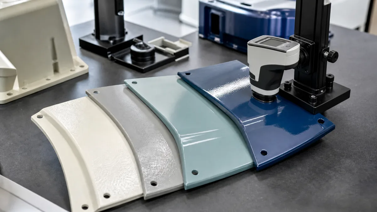
FRP color matching and finish approval should be treated as an engineering requirement—not a subjective “looks good” decision. A reliable approval process identifies the reference color, gloss range, texture, allowable variation, viewing conditions, and the specific areas of the part that must meet cosmetic standards.
For custom molded FRP parts, a purchase order that says only “match Pantone,” “black gelcoat,” or “smooth finish” leaves too much open to interpretation. Define a physical or digital standard, approve representative samples, and document how production parts will be judged before full production begins.
Define the Visual Standard Before Quotation
The best time to establish finish requirements is before requesting a quote. Finish expectations affect material selection, mold preparation, tooling cost, labor, inspection, packaging, and the feasibility of a chosen color or surface appearance.
Start with a finish specification that answers these questions:
- What is the intended color reference?
- Is the color molded into the surface, applied as paint, or both?
- What gloss level is required?
- Is the surface smooth, textured, grained, matte, or patterned?
- Which part faces are customer-visible after installation?
- Will the part be used indoors, outdoors, or in a vehicle or equipment environment?
- Does the part need to visually match metal, plastic, painted panels, or existing composite components?
- Are minor mold marks, knit lines, fiber read-through, or touch-up repairs acceptable?
- Which approved sample or document takes priority if requirements conflict?
A color code alone is usually insufficient. Pantone, RAL, and similar references can be useful starting points, but they do not fully define appearance on a molded FRP surface. The same nominal color can appear different based on resin chemistry, pigment concentration, gloss, texture, part curvature, lighting, and adjacent materials.
For outdoor components, also specify whether the finish must retain its appearance after environmental exposure. The decision between a molded gelcoat surface and a painted system has major implications for color control, repair, and field service. See this guide to gelcoat versus paint for outdoor FRP products when selecting the finish approach.
Include finish requirements in the RFQ package
A useful RFQ package includes:
- Part drawings with visible faces identified.
- A color reference, physical chip, existing mating part, or approved panel.
- Target gloss and texture requirements.
- Expected use conditions and exposure environment.
- Photos showing the installed viewing distance and surrounding materials.
- Acceptance criteria for samples and production pieces.
- Requirements for replacement parts, repairs, and batch-to-batch consistency.
This information allows a manufacturer to assess whether the requested appearance is practical with the selected molding process and part geometry.
Separate Color, Gloss, Texture and Surface Quality
“Finish” is not one characteristic. It is a combination of separate properties that should be specified and approved independently. A part can have the correct hue but still look wrong because its gloss is too high, the grain differs, or the surface reveals print-through under side lighting.
| Property | What it controls | Common approval method | Typical risk if undefined |
|---|---|---|---|
| Color | Hue, lightness, and chroma | Physical standard, approved chip, instrument reading where appropriate | Parts appear too warm, cool, light, dark, or saturated |
| Gloss | How much light the surface reflects | Gloss target or approved comparison panel | Parts look mismatched even when color is close |
| Texture | Grain, stipple, orange peel, or mold pattern | Molded sample panel or texture plaque | Visible faces look inconsistent at close range |
| Surface quality | Defects and visual uniformity | Cosmetic-zone criteria and sample comparison | Disputes over scratches, pinholes, waviness, or repairs |
Color
Specify the source of the color standard and its condition. A faded field sample, a dirty part, or an old painted panel may not be a reliable color master. If an existing component must be matched, identify whether the objective is matching its original color or its current aged appearance.
Instrumental color measurement can help establish repeatable data, but it should not replace visual approval. Spectrophotometer readings may vary with surface curvature, texture, gloss, and measurement geometry. For a visible OEM component, use measured values as a supplement to an approved physical sample.
Gloss
Gloss strongly changes perceived color. A low-gloss black may appear softer or lighter than a high-gloss black made with the same pigment. Specify gloss using a mutually agreed measurement geometry where applicable, plus a visual reference sample. A stated target without a tolerance is often incomplete.
Consider the intended installation. A very glossy surface can reveal waves, minor distortions, fingerprints, and reflected surroundings. A matte surface can better conceal some irregularities, but may be harder to repair without leaving a visible blend line.
Texture
Texture should be defined by an approved molded panel or a specified mold texture—not by a general term such as “light texture.” Texture depth, spacing, direction, and reflectivity all affect the visual result. On large parts, texture can also help mask minor cosmetic variation that would be obvious on a mirror-smooth surface.
Surface quality
Surface quality defines what can be seen, where, and under what conditions. It may include limits for:
- Pinholes, porosity, and small voids
- Gelcoat runs or thin coverage
- Fiber print-through or resin-rich areas
- Mold-release residue or contamination
- Sink, waviness, distortion, or read-through
- Scratches, chips, and handling marks
- Edge trimming quality
- Color streaks, pigment dispersion, or swirl marks
Do not require a “perfect” surface unless the application truly requires it. Instead, define observable, functional standards tied to the actual installation and viewing distance.
Create a Clear Sample and Master Hierarchy
A sample hierarchy prevents confusion when drawings, color chips, prototype parts, and production pieces do not look identical. The hierarchy should state which reference controls each aspect of the finish.
A practical hierarchy might be:
- Signed or dated finish specification
- Approved master color and texture panel
- Approved first-article part or first-article section
- Controlled color chip or standard
- CAD rendering, photograph, or marketing image
Digital renderings and photographs are useful for communication but should rarely be the final color authority. Screen calibration, lighting, image compression, and camera settings make them unreliable as acceptance masters.
Use representative samples
A flat sample coupon is valuable for confirming color and gloss, but it may not show how the finish will look on a full component. Curves, ribs, deep draws, corners, and varying wall thickness can change how reflected light reveals the surface.
For highly visible parts, approve a sample that represents the actual process, tooling surface, finish system, and geometry as closely as practical. For example, a curved exterior panel should be reviewed under conditions that reflect its end use. Buyers developing architectural cladding can apply this approach to curved FRP facade panels, where reflections and joint alignment can be especially noticeable.
Identify and protect the master
Label the approved master with a part number, revision, finish designation, approval date, and signoff authority. Store it in a protected condition away from UV exposure, contamination, heat, and handling damage. A damaged or aged master can create false rejection decisions later.
If the approved master is to be returned to the buyer, establish who retains a controlled duplicate and how future comparisons will be made.
Agree Viewing and Measurement Conditions
FRP finish approval should occur under defined viewing conditions. Without them, one inspector may reject a part viewed inches away under harsh side lighting while another accepts it at normal installation distance.
Define the following before inspection:
- Light source or lighting type
- Viewing distance
- Viewing angle
- Inspection duration
- Part orientation
- Whether the surface is clean and dry
- Ambient condition, if relevant
- Whether comparison is against a master sample or measured value
For many industrial applications, a reasonable approach is to inspect visible surfaces under diffuse, consistent lighting at the expected viewing distance. If a component will be examined closely during retail display, vehicle delivery, or architectural commissioning, that closer inspection condition should be stated.
Control metamerism
Metamerism occurs when two colors appear to match under one light source but differ under another. It is particularly important when FRP must match painted metal, injection-molded plastic, fabric, or other materials that use different pigments and binders.
If cross-material matching is critical, review samples under more than one relevant light source. Document which lighting condition is controlling if there is a tradeoff. Do not assume a match under office lighting will remain a match in daylight or under LED illumination.
Account for Materials, Process and Part Geometry
Color and finish consistency are influenced by the composite system and manufacturing route. Before fixing acceptance limits, confirm the intended surface construction and process.
Relevant variables may include:
- Pigmented gelcoat or in-mold coating
- Paint applied after molding
- Resin and reinforcement selection
- Pigment and additive compatibility
- Mold surface condition and mold texture
- Cure conditions
- Part thickness and local geometry
- Edge finishing and trimming
- Assembly features, fasteners, and bonded attachments
A smooth, high-gloss finish may be feasible on a simple panel but more difficult to maintain across a deep, complex shape with ribs, corners, and transitions. Dark colors, particularly black and deep blue, can make subtle surface waviness more visible. Metallic and pearlescent effects typically need particularly careful sample approval because viewing angle changes their appearance.
For vehicle-facing components, define the finish in relation to the surrounding body panels, grille, lamps, and trim pieces. The visual evaluation of an FRP vehicle front fascia should account for its curvature, reflected light, and the materials immediately next to it.
A manufacturability review before tooling can identify areas where a cosmetic expectation conflicts with draft, reinforcement layout, parting lines, or molding access. Resolving those issues early is usually more practical than attempting to correct them after samples are made.
Define Cosmetic Zones and Acceptance Criteria
Not every surface needs the same visual standard. Dividing the part into cosmetic zones focuses inspection effort where appearance matters and avoids unnecessary cost on hidden or functional surfaces.
A project-defined zone system might use labels such as:
- Class A: Highly visible surfaces seen at normal use distance. These receive the most stringent appearance requirements.
- Class B: Visible surfaces that are less prominent, partially shaded, or viewed less closely.
- Class C: Concealed, internal, backside, or functional surfaces where structural and dimensional requirements take priority.
These labels are not universal. Define the meaning and acceptance level of each zone in the project documents. Mark the zones on a drawing, annotated 3D model, or controlled photographs. Include edges, flange returns, openings, and transition areas; these locations are often overlooked but can become visible after assembly.
Write acceptance criteria that can be applied consistently
Useful criteria describe the type, size, quantity, and location of permitted variation. For example, rather than stating “no defects,” define whether small pinholes are acceptable in a Class B zone, whether a repair is allowed outside a Class A zone, and whether a minor color variation is acceptable between hidden backside surfaces.
Acceptance language should also distinguish between:
- A feature visible under normal inspection conditions
- A defect detectable only under magnification or extreme lighting
- A condition that affects fit, strength, sealing, or function
- A condition that is cosmetic only
Common mistakes include applying Class A standards to every square inch of a large molded part, failing to identify parting-line visibility, and using vague terms such as “commercially acceptable.” Specific, agreed criteria reduce subjective disputes.
Manage Batches, Repairs and Replacement Parts
Even with approved materials and controls, visual variation can occur across batches. The objective is not to assume every production run will be visually identical; it is to define the acceptable level of variation and the method for managing it.
For color-sensitive OEM programs, confirm:
- Whether parts must match within a single assembly or across separate shipments
- Whether production should be grouped by batch for assemblies seen together
- Whether a retained control panel is needed for each run
- How changes in pigment, coating, resin, supplier, or mold condition are communicated
- Whether replacement parts must match the original production batch or the current approved master
Replacement parts create a special challenge. A part made years after the original may match the approved master but differ from a weathered installed unit. Decide whether service parts should match the original production appearance, the current appearance standard, or a field-aged reference.
Establish repair expectations
Repairs are common discussion points because some are technically sound yet visually detectable. The approval plan should state:
- Whether cosmetic repairs are permitted in each zone
- Allowed repair types, such as filling, refinishing, or local paint touch-up
- Maximum repair size and quantity
- Whether repairs require disclosure or buyer review
- How repaired areas will be inspected for color, gloss, texture, and adhesion
A repair that is acceptable on an internal mounting flange may be unacceptable on a highly visible exterior face. Set these rules before production rather than deciding after a part is complete.
Document First-Article and Production Approval
First-article approval confirms that a representative part meets the agreed visual and functional requirements before routine production proceeds. It should not rely on informal email comments alone.
A first-article finish approval record can include:
- Part number, revision, and finish designation
- Material and surface system identification
- Approved color, gloss, texture, and master sample references
- Cosmetic-zone drawing
- Inspection conditions
- Photos of the approved part, including key visual areas
- Measured results, if measurement is part of the requirement
- Approved deviations, limitations, or repair allowances
- Signoff names, dates, and revision control
After first-article approval, production inspection should compare parts to the same documented requirements. If a process, material, mold surface, or finish system changes, determine whether a new sample review is needed before affected parts are accepted.
For custom programs, GFIND can review buyer drawings and application requirements, support prototype and molded-part development, and inspect finished parts against agreed references. The most useful starting point is a controlled finish package rather than a color name alone.
FAQ
Can FRP match a painted metal or plastic part?
It can be matched closely within an agreed standard, but exact visual identity in every light source is not always realistic. Differences in material, gloss, texture, pigment system, and part geometry can affect perceived color. Approve physical samples side by side under the relevant lighting conditions.
Is a Pantone or RAL number enough for FRP color matching?
Usually not. It identifies a target color direction, but does not define gloss, texture, surface reflection, aging condition, or acceptable tolerance. Pair the code with an approved physical reference and written finish criteria.
Should color be approved before or after production tooling is made?
Approve the general color and finish concept before tooling. Then approve a molded, representative sample after tooling because the actual mold surface and process can influence final appearance.
What should be included in an FRP finish approval package?
Include the controlling reference sample, finish specification, cosmetic-zone drawing, viewing conditions, allowable variation, repair rules, first-article approval record, and process-change notification requirements.
A well-defined FRP color matching and finish approval plan helps protect appearance and reduce schedule risk by turning subjective expectations into measurable, reviewable requirements. If you are preparing an RFQ for a custom composite part, contact GFIND with drawings, finish references, intended use conditions, and cosmetic-zone requirements for a manufacturability-focused review.