FRP case studies
Equipment covers, architectural panels, tanks and molded components. See how we develop the shape, connections and finish around each application.
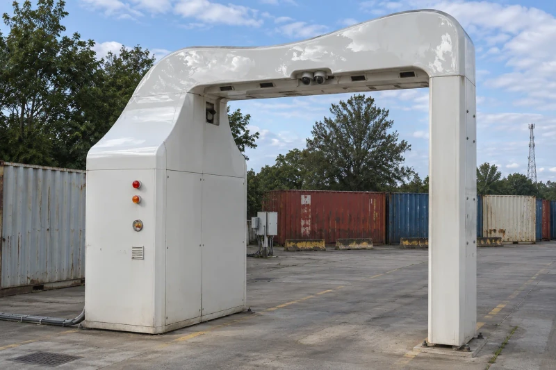
Three-section GRP scanner enclosure.
Tooling-located fixing points, section joints and removable service covers for a three-part GRP scanner enclosure.
View case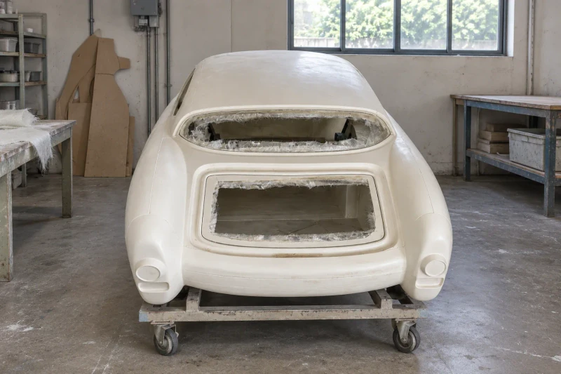
An EV body design made ready for its first fit.
Full-size forms turn the exterior design into molded body sections that can be checked with the chassis.
View case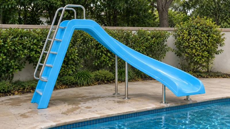
A pool-slide package that meets at the joints.
The chute route, outlet and support contacts follow the pool layout and are brought together during trial fitting.
View case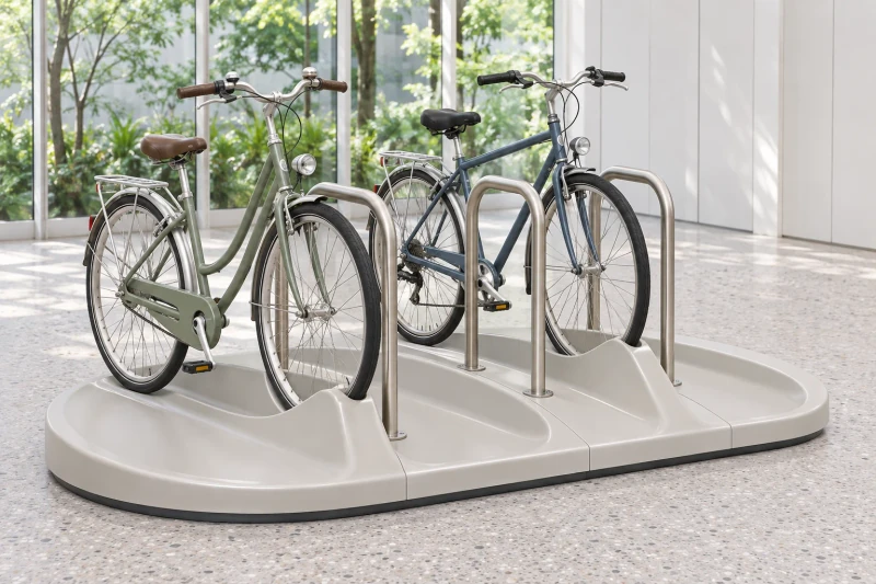
Bicycle parking shaped around the room.
Molded sections bring wheel spacing, retaining fittings and the available floor plan together. Images are concept visualizations of possible layouts and fabrication details.
View case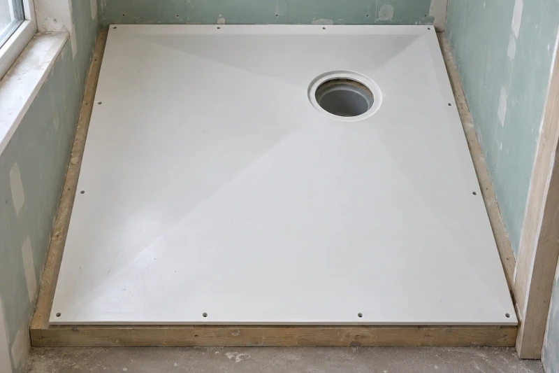
Floor formers developed around one drain detail.
The molded fall, outlet recess and perimeter fixing layout are settled on the sample before batch supply.
View case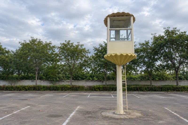
A shell-shaped exterior that fits around the cabin.
Ribbed lower panels and the scalloped top follow the cabin structure while leaving its windows and entrance clear.
View case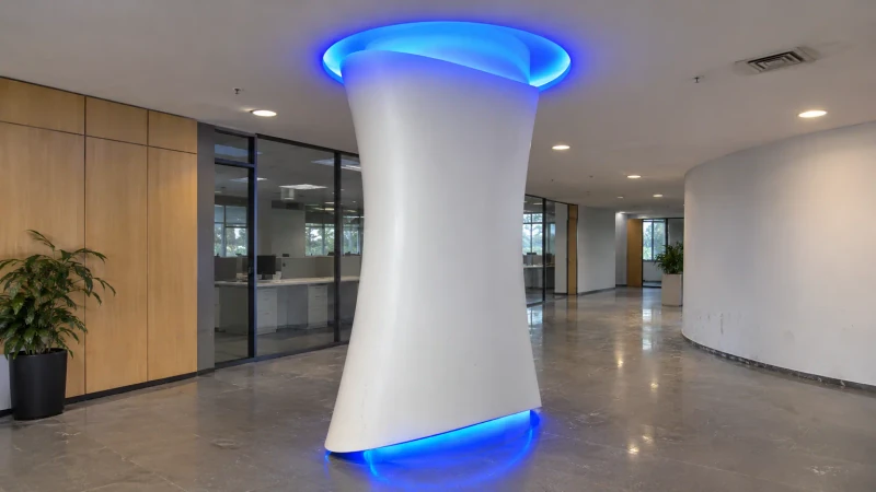
Curved column panels that follow the room.
The decorative profile, panel divisions and lighting access are developed around the measured column.
View case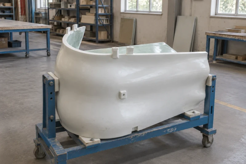
Blade shells with the seams and attachment points built in.
The RTM tooling, laminate and joined edges follow the same released component design.
View case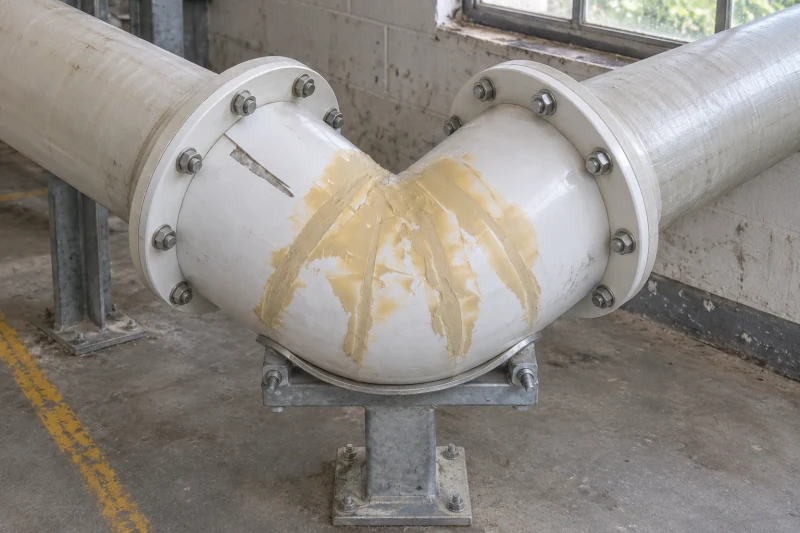
Pipe bends that meet the route at both ends.
Bend geometry and flange orientation are considered together, reducing separate adjustments during fit-up.
View case
Duct sections prepared for the surveyed extraction route.
Bends, flange orientations and joint positions follow the equipment connections and site handling limits.
View case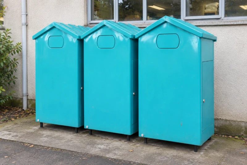
A collection bank built around the emptying routine.
Donation access, internal storage and the collection door are developed together in one molded body.
View case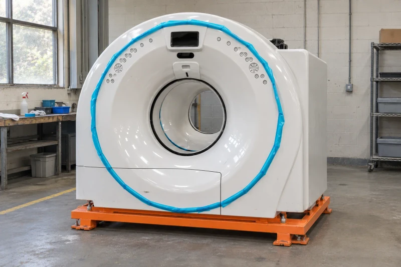
CT covers that open without losing the curve.
A continuous curved exterior combines with removable panels and concealed mounting areas.
View case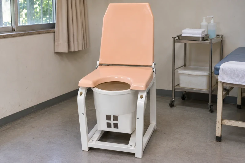
Chair covers developed around the frame and its access points.
Upper and lower panels share a coordinated exterior while retaining the openings and removal paths the equipment needs.
View case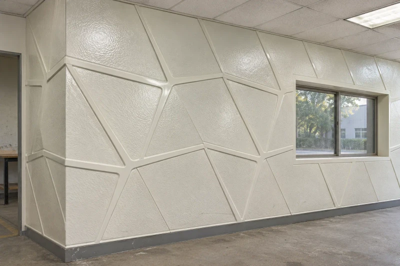
A textured wall that comes together panel by panel.
The molded pattern follows the whole elevation, including adjoining edges and changes of direction.
View case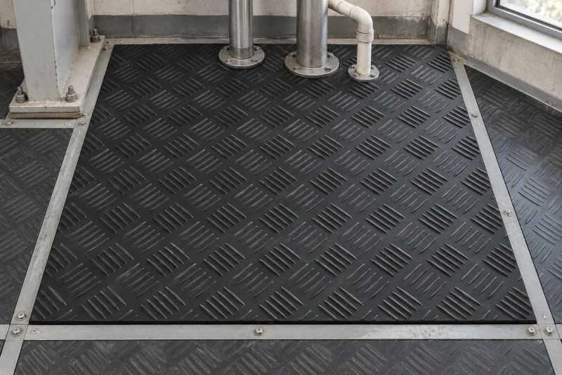
Floor panels divided around the equipment.
Cutouts, support ribs and lift-out sections are prepared for the platform layout rather than trimmed at random on site.
View case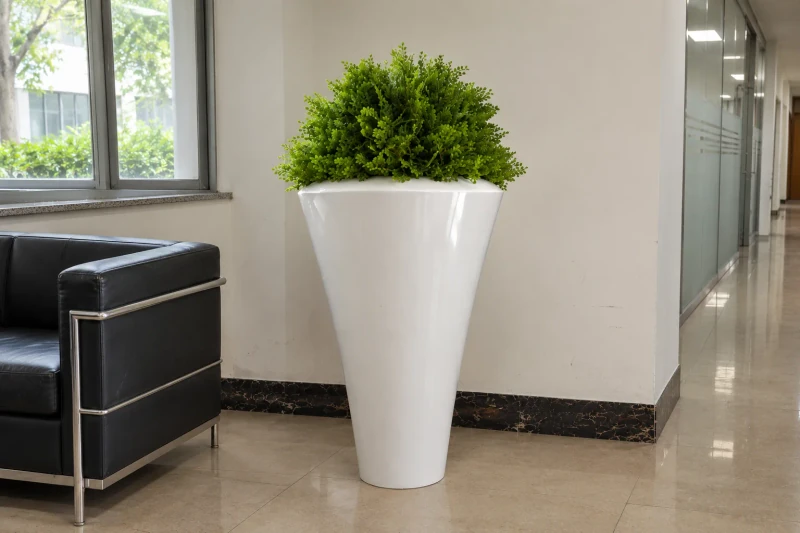
A tapered planter shaped around the planting scheme.
The exterior profile, usable depth and drainage arrangement are developed as one molded shell.
View case
Pebble seating shaped for the landscape plan.
Sitting height, footprint and underside supports are developed alongside the rounded exterior.
View case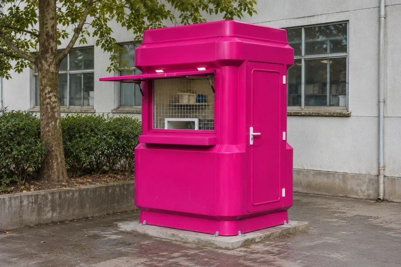
A sales booth built around the service window.
Counter height, operator access and moving fittings are planned with the molded shell.
View case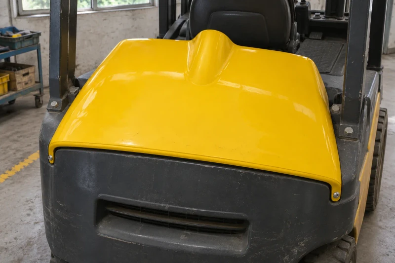
A forklift cover that clears the machine beneath it.
The raised crown, perimeter trim and reinforced fixing areas follow the machine and its removal route.
View case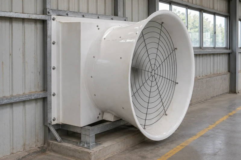
A fan housing that fits the rotor, guard and frame.
The inlet profile and mounting areas follow the fan assembly, with access for removing the guard.
View case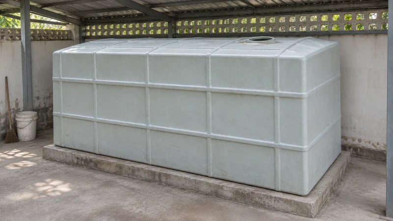
Water storage shaped around a restricted space.
The rectangular body combines the available footprint with reinforcing ribs, top access and planned pipe connections.
View case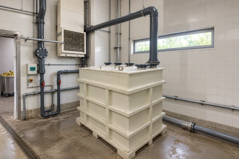
A slurry tank that fits the process room.
The vessel envelope, process connections and cleaning access are coordinated before fabrication.
View case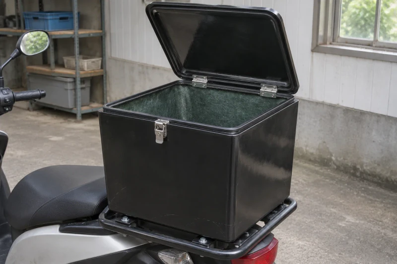
A delivery-box body and lid developed as a pair.
The closure rim, useful inside space and carrier fixing areas follow one box arrangement.
View case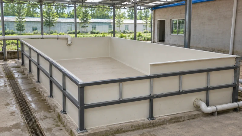
An aquaculture tank fitted to the farm layout.
Working depth, water connections and support contacts are coordinated with the site's installation route.
View case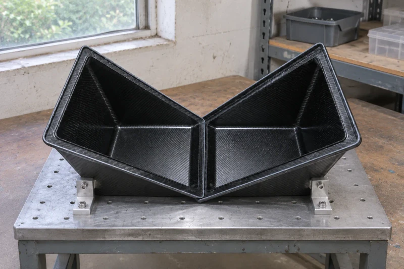
Carbon shells with fit and surface appearance considered together.
Mating rims, trimmed edges and fabric appearance are reviewed on the same shell geometry.
View case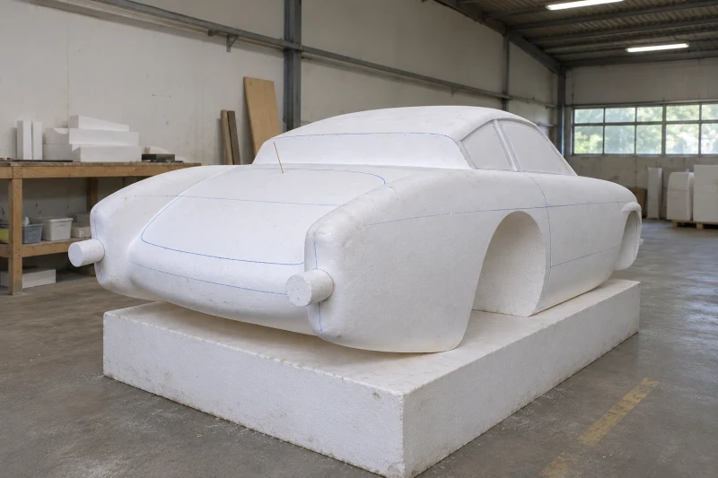
See the coupe body at full size before tooling.
A physical foam master brings the curves and opening positions into one reviewable reference.
View case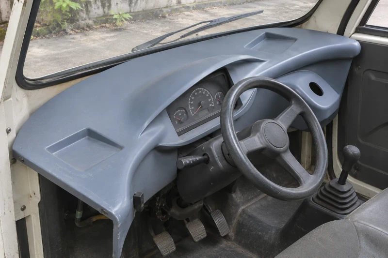
A dashboard that makes room for the cabin equipment.
Instrument apertures, molded recesses and control clearances are settled before repeat parts are made.
View case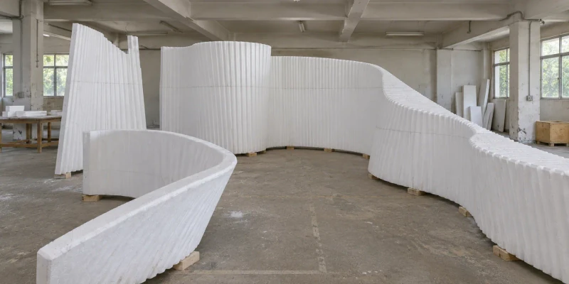
A full-size reference for a changing interior curve.
Arranged foam profiles let the design team review height changes and transitions together before developing the final panels.
View case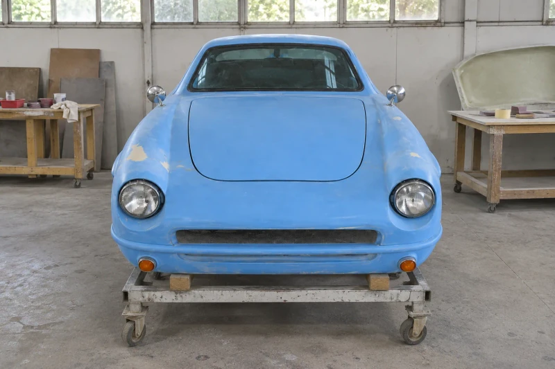
Set the coupe body fit before the final surface treatment.
Opening panels, lamps and glazing are reviewed in the same assembly before surface work continues.
View case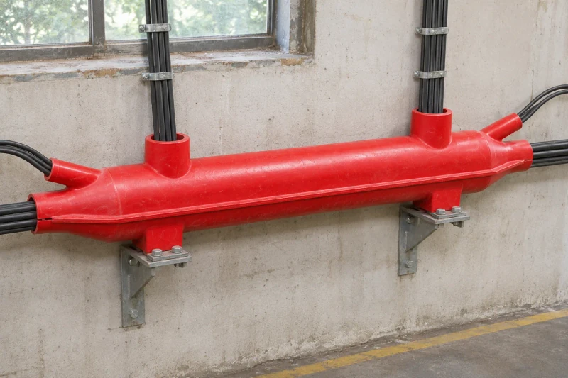
Split shells that follow the cable route.
The main body opens around the cable bundle, with joining access and branch-end fitting considered before molding.
View case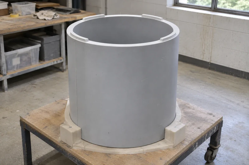
A foam-core shell with the wall and joints developed together.
Bore clearance, outer diameter and the core-and-skin construction follow the mating assembly.
View case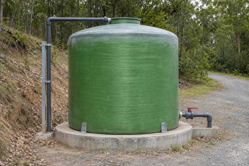
Reserve-water storage sized to the site plan.
Working volume, draw-off connections and delivery constraints guide the tank body together.
View case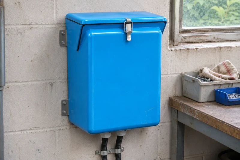
An equipment box that makes room for the assembly.
The body depth, lid edges and fixing provisions are developed around equipment access and the selected closure fittings.
View case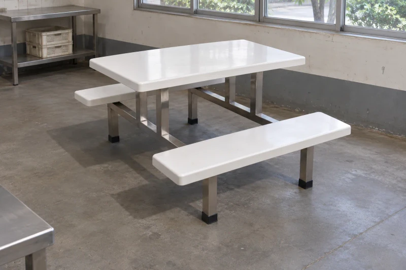
Table and bench panels that share one assembly layout.
Seating positions, tabletop size and underside fixing areas are coordinated with the connected frame.
View case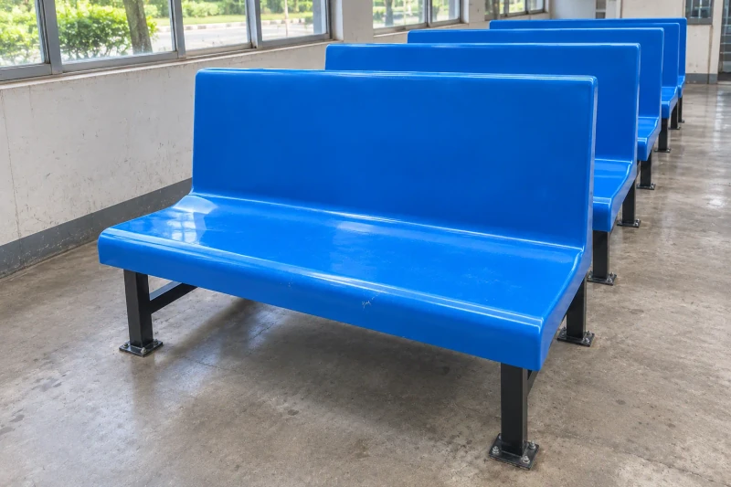
Bench shells matched to the seating plan and supports.
Molded seat sections and optional backs follow the layout, with underside fixing areas prepared for the chosen frame.
View case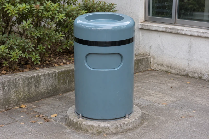
A bin shell designed around usable space.
The inner container, deposit opening and emptying access determine the molded body layout together.
View case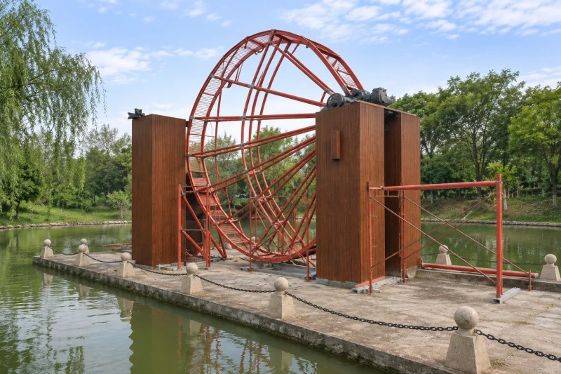
Wood-grain covers that leave the mechanism accessible.
Shaped exterior panels conceal the supports while retaining separate inspection access.
View case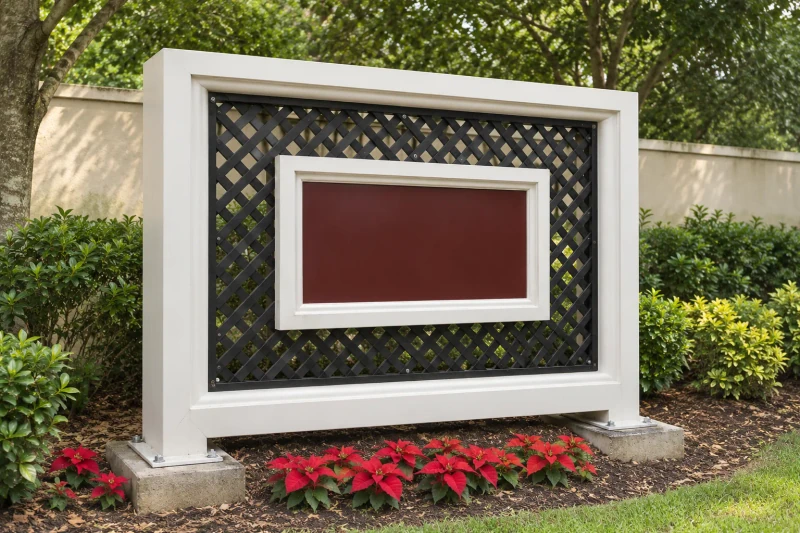
A molded sign frame around the chosen display.
The exterior profile, display opening and support fixing areas follow one sign arrangement.
View case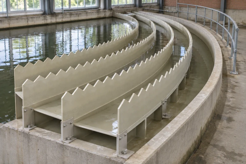
Basin modules that share one crest and fixing reference.
Curved channels, notched plates and support contacts follow the process layout together.
View case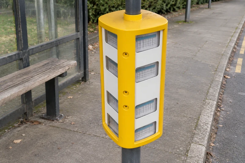
One housing for the display and its support.
Panel openings, the mounting collar and replacement access follow the same housing design.
View case